Delta Electronics Programmable Logic Controller DVP-PLC User Manual
Page 436
8 Application Instructions API 100-149
DVP-PLC Application Manual
8-34
API Mnemonic
Operands
Function
123
D EDIV P
Floating Point Division
Controllers
ES/EX/SS SA/SX/SC EH/SV
Bit Devices
Word Devices
Program Steps
Type
OP
X Y M S K H
KnX
KnY KnM KnS T
C
D
E
F
S
1
*
*
*
S
2
*
*
*
D
*
DEDIV, DEDIVP: 13 steps
PULSE 16-bit 32-bit
ES EX SS SA SX SC EH SV ES EX SS SA SX SC EH SV ES EX SS SA SX SC EH SV
Operands:
S
1
: Dividend S
2
: Divisor D: Quotient and remainder
Explanations:
1. See the specifications of each model for their range of use.
2. Flags: M1020 (zero flag); M1021 (borrow flag); M1022 (carry flag)
3. S
1
÷ S
2
= D. The floating point value in the register designated by S
1
is divided by the floating point value in the
register assigned by S
2
and the result is stored in the register designated by D. The division is conducted in
binary floating point system.
4. If
S
1
or S
2
is an designated constant K or H, the instruction will convert the constant into a binary floating point
value before the operation.
5. If
S
2
= 0, operation error will occur, the instruction will not be executed, M1067, M1068 = On and D1067 will
recorded the error code H’0E19.
6. If the absolute value of the result > maximum floating point available, the carry flag M1022 = On.
7. If the absolute value of the result < minimum floating point available, the borrow flag M1021 = On.
8. If the result = 0, the zero flag M1020 = On.
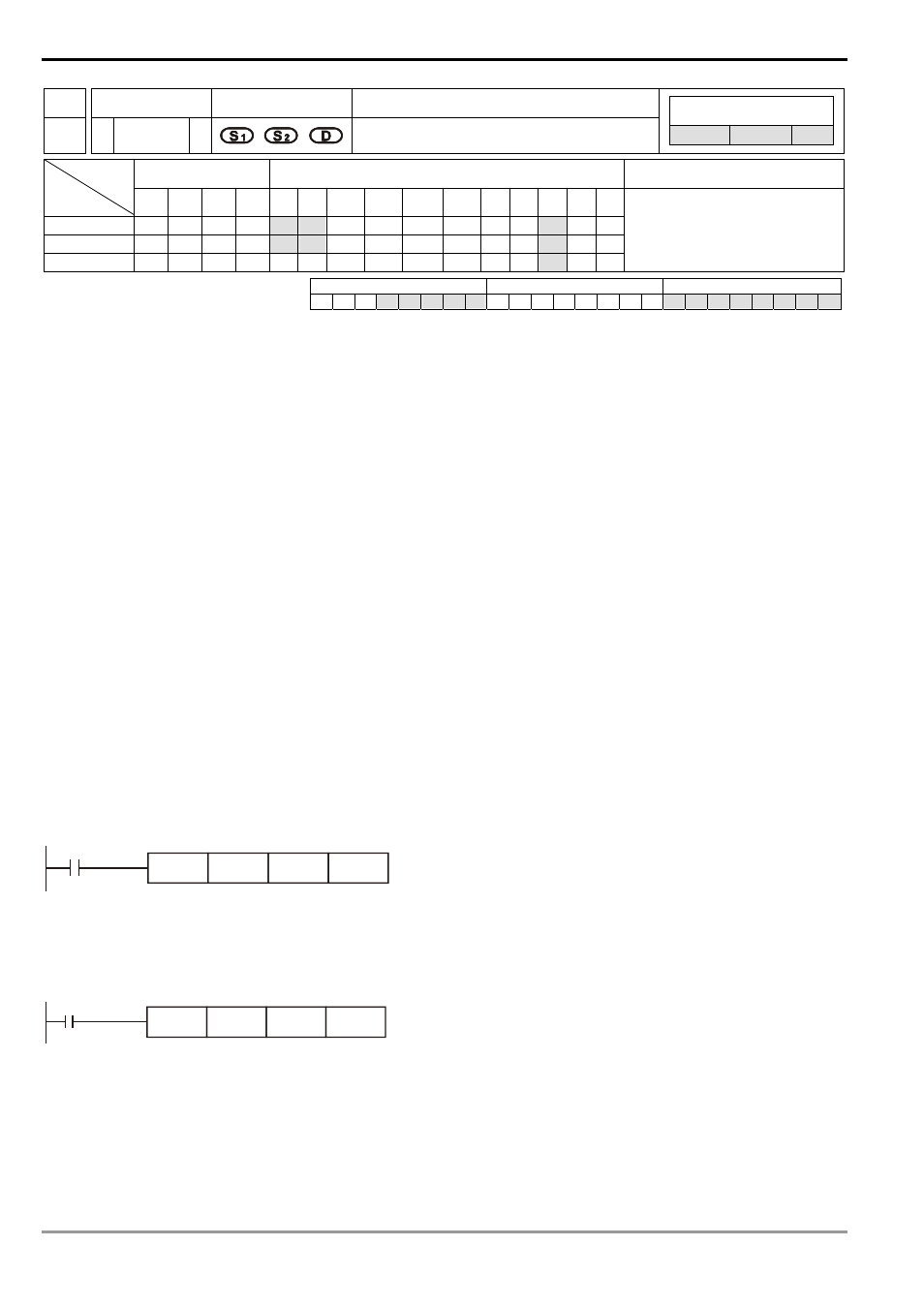
Program Example 1:
When X1 = On, binary floating point (D1, D0) ÷ binary floating point (D11, D10) and the quotient is stored in (D21,
D20).
D0
DEDIV
X1
D10
D20
Program Example 2:
When X2 = On, binary floating point (D1, D0) ÷ K1234 (automatically converted into binary floating point) and the
result is stored in (D11, D10).
X2
DEDIV
D0
K1234
D10
Remarks:
For floating point operations, see “5.3 Handling of Numeric Values”.