Delta Electronics Programmable Logic Controller DVP-PLC User Manual
Page 367
7 Application Instructions API 50-99
D V P - P L C A P P L I C AT I O N M A N U A L
7-83
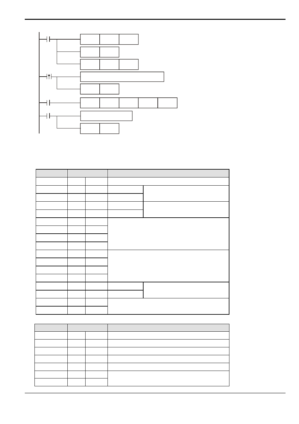
MOV
D1120
H86
M1002
SET
M1120
SET
M1122
MOV
D1129
K100
X10
M1123
RST
M1123
RS
D100
K17
D120
K35
Process of received data
Set up communication protocol 9600,7,E,1
Retain communication protocol
Set up communication time-out 100ms
Write in data to be transmitted in advance
Set up sending request
Receiving of data is completed.
The flag is reset.
Sending request
pulses
Receiving
completed
PLC Ö VFD-B, PLC sends “: 01 03 2101 0006 D4 CR LF “
VFD-B Ö PLC, PLC receives “: 01 03 0C 0100 1766 0000 0000 0136 0000 3B CR LF “
Registers for sent data (PLC sends out message)
Register
Data
Explanation
D100 low
‘: ’
3A H
STX
D100 high
‘0’
30 H
ADR 1
D101 low
‘1’
31 H
ADR 0
Address of AC motor drive: ADR
(1,0)
D101 high
‘0’
30 H
CMD 1
D102 low
‘3’
33 H
CMD 0
Instruction code: CMD (1,0)
D102 high
‘2’
32 H
D103
low
‘1’ 31
H
D103 high
‘0’
30 H
D104 low
‘1’
31 H
Start data address
D104 high
‘0’
30 H
D105 low
‘0’
30 H
D105 high
‘0’
30 H
D106 low
‘6’
36 H
Number of data (counted by words)
D106 high
‘D’
44 H
LRC CHK 1
D107 low
‘4’
34 H
LRC CHK 0
Error checksum: LRC CHK (0,1)
D107 high
CR
D H
D108 low
LF
A H
END
Registers for received data (VFD-B responds with messages)
Register
Data
Explanation
D120 low
‘: ’
3A H
STX
D120 high
‘0’
30 H
ADR 1
D121 low
‘1’
31 H
ADR 0
D121 high
‘0’
30 H
CMD 1
D122 low
‘3’
33 H
CMD 0
D122 high
‘0’
30 H
D123 low
‘C’
43 H
Number of data (counted by byte)