Delta Electronics Programmable Logic Controller DVP-PLC User Manual
Page 356
7 Application Instructions API 50-99
D V P - P L C A P P L I C AT I O N M A N U A L
7-72
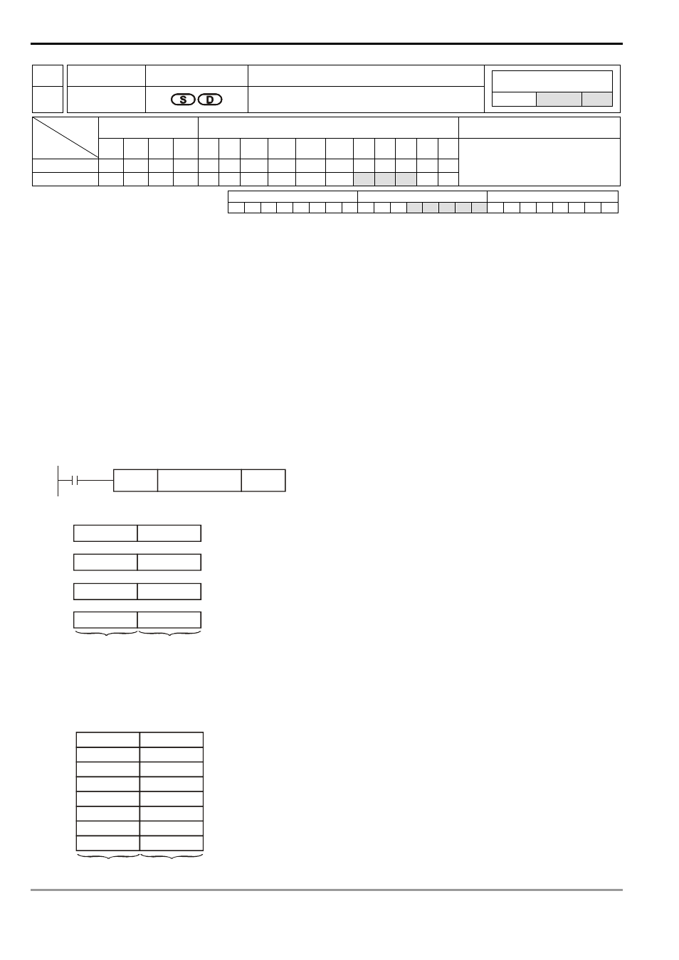
API Mnemonic
Operands
Function
76
ASC
ASCII Code Conversion
Controllers
ES/EX/SS SA/SX/SC EH/SV
Bit Devices
Word Devices
Program Steps
Type
OP
X Y M S K H
KnX
KnY KnM KnS T
C
D
E
F
S
D
*
*
*
ASC: 11 steps
PULSE 16-bit 32-bit
ES EX SS SA SX SC EH SV ES EX SS SA SX SC EH SV ES EX SS SA SX SC EH SV
Operands:
S
: English letter to be converted into ASCII code D: Device for storing ASCII code
Explanations:
1. S: enter 8 Engligh letters by using WPLSoft on computer or enter ASCII code by HPP.
2. See the specifications of each model for their range of use.
3. Flag: M1161 (8/16 bit mode switch)
4. If the execution of this instruction is connected to a 7-segment display, the error message can be displayed by
English letters.
Program Example:
1. When X0 = On, convert A ~ H into ASCII code and stored it in D0 ~ D3.
X0
ASC
A B C D E F G H
D0
D0
D1
D2
b15
b0
42H (B)
41H (A)
44H (D)
43H (C)
46H (F)
45H (E)
D3
48H (H)
47H (G)
Lower 8 bits
Upper 8 bits
2. When M1161 = On, every ASCII code converted from the letters will occupy the lower 8 bits (b7 ~ b0) of a
register. The upper 8 bits are invalid (filled by 0). One register stores a letter.
b15
b0
D0
D2
D4
D6
D1
D3
D5
D7
00 H
00 H
00 H
00 H
00 H
00 H
00 H
00 H
41H (A)
42H (B)
43H (C)
44H (D)
45H (E)
46H (F)
47H (G)
48H (H)
Lower 8 bits
Upper 8 bits