3 basic instructions – Delta Electronics Programmable Logic Controller DVP-PLC User Manual
Page 168
3 Basic Instructions
DVP-PLC Application Manual
3-14
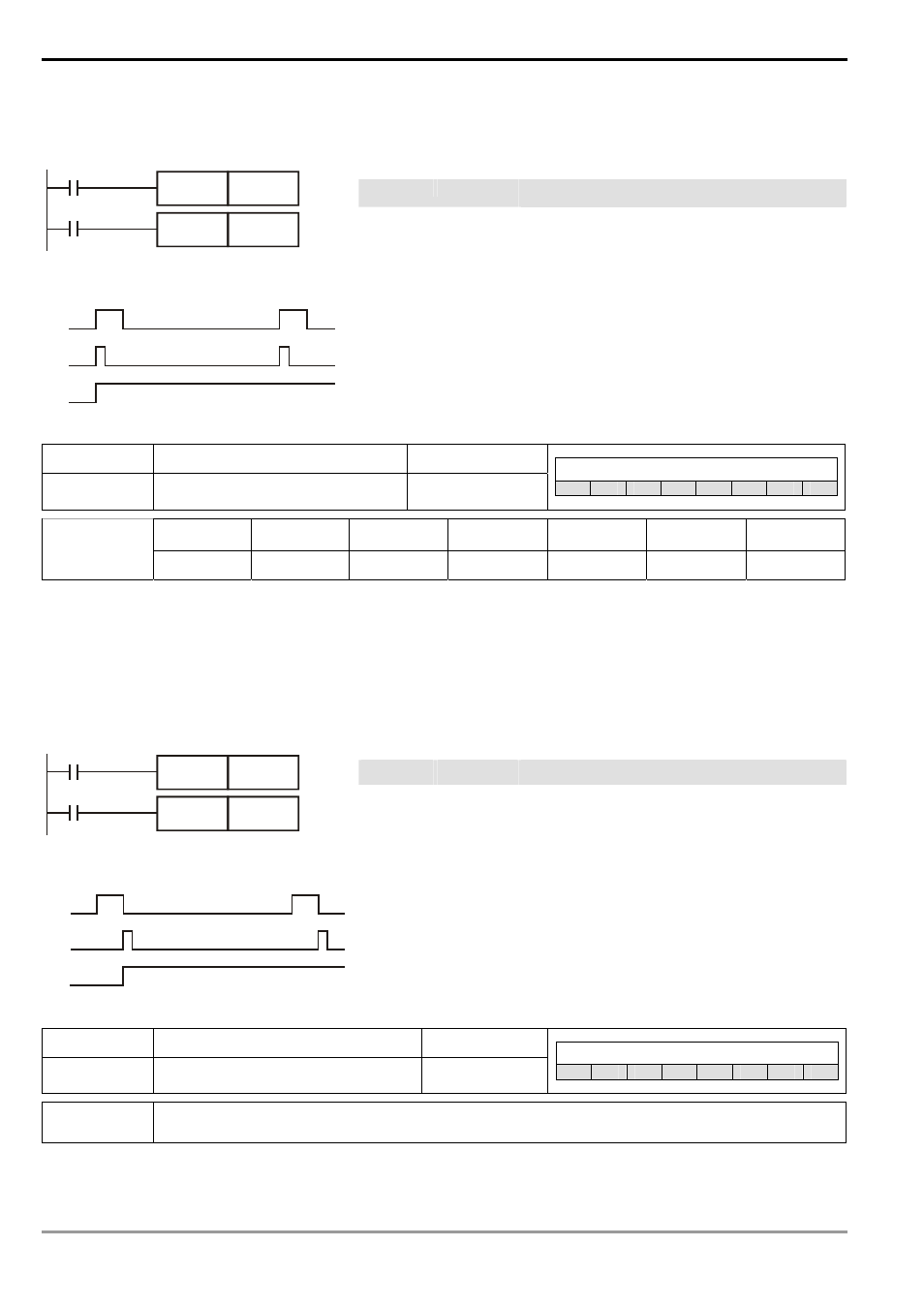
Program Example:
Ladder diagram:
Instruction code:
Operation:
LD X0 Loading in A contact of X0
PLS
M0
M0 rising-edge output
LD M0 Loading in contact A of M0
X0
M0
PLS
M0
Y0
SET
Timing Diagram:
X0
M0
Y0
1 scan time
SET Y0
Y0 latched (On)
Mnemonic Function Program
steps
PLF
Falling-edge output
1
Controllers
ES
EX
SS
SA
SX
SC
EH
SV
X0 ~ X377
Y0 ~ Y377 M0 ~ M4095 S0 ~ S1023
T0 ~ T255
C0 ~ C255 D0 ~ D9999
Operand
-
9
9
-
-
-
-
Explanations:
When X0 goes from On to Off (falling-edge trigger), PLF instruction will be executed and S will send out pulses for
once of 1 scan time.
Program Example:
Ladder diagram:
Instruction code:
Operation:
LD
X0
Loading in A contact of X0
PLF
M0
M0 falling-edge output
LD
M0
Loading in contact A of M0
X0
M0
PLF
M0
Y0
SET
Timing Diagram:
1 scan time
X0
M0
Y0
SET Y0
Y0
latched
(On)
Mnemonic Function
Program
steps
END
Program End
1
Controllers
ES
EX
SS
SA
SX
SC
EH
SV
Operand
N/A
Explanations:
- 1x9 Bi-Directional Transceiver Module OPBD-155F2J1R (7 pages)
- Single Mode SFP Transceiver LCP-1250B4MDRx (14 pages)
- LC-1250xxxx Series (10 pages)
- Human Machine Interface DOP-AS Series (329 pages)
- Analog Output Module DVP04DA-S (2 pages)
- DeviceNet Slave Communication Module IFD9502 (2 pages)
- LCP-155B4MSRx (12 pages)
- High-Speed PCI 12-Axis Motion Control Card PCI-DMC-B01 (528 pages)
- Network Device DVP01PU-S (2 pages)
- GBIC-1250D5MR (12 pages)
- SPBD-1250A4Q1RT (10 pages)
- SILM4015 (1 page)
- LCP-8500A4EDR (14 pages)
- 10GBASE-SR SFP+ Optical Transceiver LCP-10G3A4EDR (16 pages)
- LCP-155A4HSRx (11 pages)
- LCP-1250RJ3SR-L (9 pages)
- SILM320L (1 page)
- LCP-1250RJ3SR-S (9 pages)
- SIL530 (1 page)
- Extension Digital I/O Module DOP-EXIO28RAE (1 page)
- DVP Series PLC DVP04TC-H2 (2 pages)
- 1x9 Bi-Directional Transceiver Module OPBD-155F1J1R (7 pages)
- Distribution Box TAP-CN01/02/03 (2 pages)
- LCP-200A4HSR (9 pages)
- Pulse Generation Unit DVP01PU-H2 (2 pages)
- Power Connection Interface VFD-PSD01 (1 page)
- Programmable Logic Controller DVP04DA-H2 (2 pages)
- Single Mode SFP Transceiver LCP-1250B4QDRx (13 pages)
- LCP-155B4JSRx Series (12 pages)
- Series Temperature Controller DTD Series (2 pages)
- Brake Modules BUE Series (2 pages)
- PLC DVP Series DVP-SX (2 pages)
- Digital Keypad / Display ASD-PU-01A (1 page)
- Multimode SFP Transceiver LCP-1250A4FDRx (14 pages)
- HMU1362M (1 page)
- RPA-01 (1 page)
- THMR1395 (1 page)
- SFBD-155F2J1RM (7 pages)
- Program Transfer Module DVP-PCC01 (1 page)
- RTU-DNET (41 pages)
- AC Servo Drive ASDA-AB (37 pages)
- Digital Keypad / Display ASD-PU-01B (1 page)
- HMR1045 (1 page)
- CANopen Communication Module DVPCOPM-SL (2 pages)
- SPBD-1250B4Q1R (10 pages)