Wiring for dip swich input, Remarks: 1. when n = k1, d, Will occupy one register. when n = k2, d – Delta Electronics Programmable Logic Controller DVP-PLC User Manual
Page 349
7 Application Instructions API 50-99
D V P - P L C A P P L I C AT I O N M A N U A L
7-65
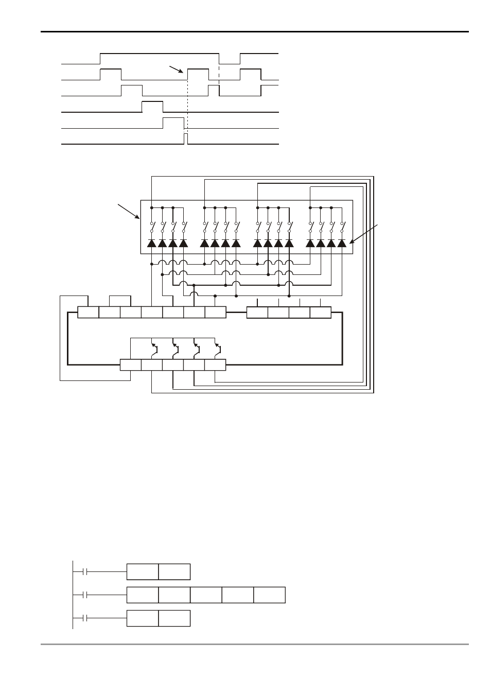
X10
Y20
Y21
Y22
Y23
M1029
0.1s
0.1s
0.1s
0.1s
0.1s
0.1s
Interruption
Execution completed
Cyclic operation
4. Wiring for DIP swich input:
S/S
X20
X21
X22
X23
X24
X25
X26
X27
Y23
Y22
Y21
Y20
C
1
2
4
8
1
2
4
8
PLC
10
10
10
10
0
1
2
3
10
0
10
1
10
2
10
3
0V
+24V
DIP switches for
BCD wiring
Must connect to a
diode (1N4148) in
series
The first group
The second group
Remarks:
1. When
n
= K1, D
2
will occupy one register. When n = K2, D
2
will occupy 2 consecutive registers.
2. Follow the methods below for the transistor scan output:
a) When X10 = On, DSW instruction will be executed. When X10 goes Off, M10 will keep being On until the
scan output completes a scan cycle and go Off.
b) When X10 is used as a button switch, whenever X10 is pressed once, M10 will be reset to Off when the scan
output designated by DSW instruction completes a scan cycle. The DIP switch data will be read completely
and the scan output will only operate during the time when the button switch is pressed. Therefore, even the
scan output is a transistor type, the life span of the transistor can be extended because it does not operate
too frequently.
M10
DSW
X20
Y20
D20
K2
X10
SET
M10
M1029
RST
M10