1 basic principles of plc ladder diagram – Delta Electronics Programmable Logic Controller DVP-PLC User Manual
Page 23
1 Basic Principles of PLC Ladder Diagram
DVP-PLC Application Manual
1-19
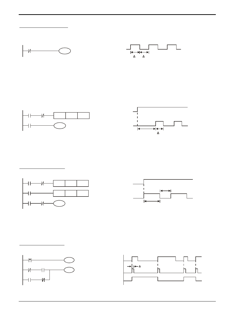
Example 8: Oscillating circuit
An oscillating circuit with cycle ΔT+ΔT
Y1
Y1
Y1
T
T
The ladder diagram above is a very simple one. When the program starts to scan the normally closed contact
Y1, Y1 will be closed because coil Y1 is Off. When the program then scan to coil Y1 and make it On, the output will be
1. When the program scans to the normally closed contact Y1 again in the next scan cycle, because coil Y1 is On, Y1
will be open and make coil Y1 Off and output 0. The repeated scans will result in coil Y1 outputs oscillating pulses by
the cycle ΔT(On)+ΔT(Off).
An oscillating circuit with cycle nT+ΔT
T0
X0
TMR
Y1
Y1
T0
Kn
Y1
T
T
n
X0
The ladder diagram program controls the On time of coil Y1 by timer T0 and disable timer T0 in the next scan
cycle, resulting in the oscillating pulses in the output of Y1. n refers to the decimal set value in the timer and T is the
cycle of the clock.
Example 9: Flashing circuit
T2
TMR
Kn2
T1
X0
TMR
Y1
T2
T1
Kn1
X0
T1
Y1
T
n1
X0
T
n2
*
*
The ladder diagram is an oscillating circuit which makes the indicator flash or enables the buzzer alarms. It
uses two timer to control the On/Off time of coil Y1. n1 and n2 refer to the set values in T1 and T2 and T is the cycle
of the clock.
Example 10: Trigger circuit
Y1
M0
X0
Y1
Y1
M0
M0
X0
M0
Y1
T