Delta Electronics Programmable Logic Controller DVP-PLC User Manual
Page 350
7 Application Instructions API 50-99
D V P - P L C A P P L I C AT I O N M A N U A L
7-66
API Mnemonic Operands
Function
73
SEGD P
Seven Segment Decoder
Controllers
ES/EX/SS SA/SX/SC EH/SV
Bit Devices
Word Devices
Program Steps
Type
OP
X Y M S K H
KnX
KnY KnM KnS T
C
D
E
F
S
*
*
*
*
*
*
*
*
*
*
*
D
*
*
*
*
*
*
*
*
SEGD, SEGDP: 5 steps
PULSE 16-bit 32-bit
ES EX SS SA SX SC EH SV ES EX SS SA SX SC EH SV ES EX SS SA SX SC EH SV
Operands:
S
: Source device to be decoded D: Output device after the decoding
Explanations:
See the specifications of each model for their range of use.
Program Example:
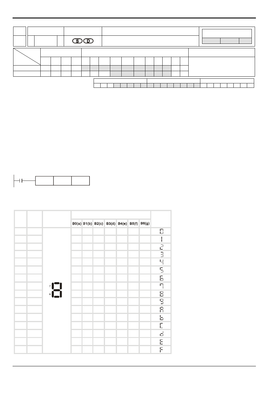
When X10 = On, the contents (0 ~ F in hex) of the lower 4 bits (b0 ~ b3) of D10 will be decoded into a 7-segment
display for output. The decoded results will be stored in Y10 ~ Y17. If the content exceeds 4 bits, the lower 4 bits are
still used for the decoding.
X10
SEGD
D10
K2Y10
Decoding table of the 7-segment display:
0
1
2
3
4
5
6
7
8
9
A
B
C
D
E
F
1111
1110
1101
1100
1011
1010
1001
1000
0111
0110
0101
0100
0011
0010
0001
0000
ON
OFF
ON
ON
ON
ON
ON
OFF
OFF
OFF
OFF
OFF
ON
ON
ON
ON
ON
ON
OFF
OFF ON
ON
ON
ON
ON
ON
OFF
OFF
OFF
OFF
OFF
ON
ON
ON
ON
ON
OFF ON
ON
OFF
ON
ON
OFF ON
ON
ON
ON
ON
ON
ON
ON
OFF
OFF
OFF
ON
ON
ON
ON
ON
ON
ON
ON
ON
ON
ON
ON
ON
OFF
ON
ON
OFF OFF ON
ON
ON
OFF
ON
ON
ON
OFF
ON
OFF OFF ON
ON
ON
ON
OFF OFF OFF
a
c
b
d
g
ON
ON
ON
ON
ON
ON
OFF
ON
ON
ON OFF
ON
OFF
OFF ON
ON
ON
ON
ON
ON
ON
ON
Hex
Bit
combi-
nation
Composition
of the 7-
segment display
Status of each segment
Data
displayed