3 functions and features of file registers, 2 functions of devices in dvp-plc – Delta Electronics Programmable Logic Controller DVP-PLC User Manual
Page 58
2 Functions of Devices in DVP-PLC
DVP-PLC Application Manual
2-30
When you use index register E, F to modify the operands, the modification range CANNOT exceed the range of
special purpose registers D1000 ~ D1999 and special auxiliary registers M1000 ~ M1999 in case errors may occur.
2.8.3 Functions and Features of File Registers
When the power of PLC is switched on, SA/SX/SC and EH/EH2/SV series MPU will check the following devices:
1. M1101 (whether the file register is enabled)
2. D1101 (No. of file registers in SA/SX/SC series MPU: K0 ~ K1,599; No. of file registers in EH/EH2/SV series MPU:
K0 ~ K9,999)
3. D1102 (Number of file registers to be read in SA/SX/SC series MPU: K0 ~ K1,600; number of file registers to be
read in EH/EH2/SV series MPU: K0 ~ K8,000)
4. D1103 (devices for storing the data read from file registers; the No. of designated data register D starts from
K2,000 ~ K9,999; determining whether to automatically send the content in the file register to the designated data
register.)
Note:
1. When D1101 of SA/SX/SC series MPU is bigger than 1,600, D1101 of EH/EH2/SV series MPU is bigger than
8,000 and D1103 is smaller than 2,000 or bigger than 9,999, the data read from file registers will not be sent to
data register D.
2. When the program starts to send the data read from the file register to data register D and the address of the file
register or the data register D exceed their ranges, PLC will stop the reading.
3. There are 1,600 file registers in SA/SX/SC series MPU and 10,000 in EH/EH2/SV series MPU. The file register
does not have an exact device No.; therefore the read/write function of file registers has to be executed by
instruction API 148 MEMR, API 149 MEMW or through peripheral devices HPP and WPLSoft.
4. If you tend to read a file register with an address that is not within the range, the read value will be “0”.
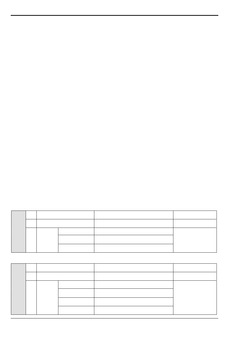
2.9 Pointer [N], Pointer [P], Interruption Pointer [I]
ES/EX/SS series MPU:
N For master control loop
N0 ~ N7, 8 points
Control point of master
control loop
P For CJ, CALL instructions
P0 ~ P63, 64 points
Position pointer of CJ,
CALL
External interruption I001, I101, I201, I301, 4 points
Timed interruption
I6□□, 1 point (□□=10 ~ 99, time base = 1ms)
(for V5.7)
Pointer
I
Interruption
Communication
interrupt
I150, 1 point
Position pointer of
interruption subroutine
SA/SX/SC series MPU:
N Master control loop
N0 ~ N7, 8 points
Control point of master
control loop
P For CJ, CALL instructions
P0 ~ P255, 256 points
Position pointer of CJ,
CALL
External interruption I001, I101, I201, I301, I401, I501, 6 points
Timer interruption
I6□□, I7□□, 2 points (□□ = 1 ~ 99, time
base = 1ms)
High-speed counter
interruption
I010, I020, I030, I040, I050, I060, 6 points
Pointer
I Interruption
Communication
interruption
I150, 1 point
Position pointer of
interruption subroutine