1 basic principles of plc ladder diagram – Delta Electronics Programmable Logic Controller DVP-PLC User Manual
Page 6
1 Basic Principles of PLC Ladder Diagram
DVP-PLC Application Manual
1-2
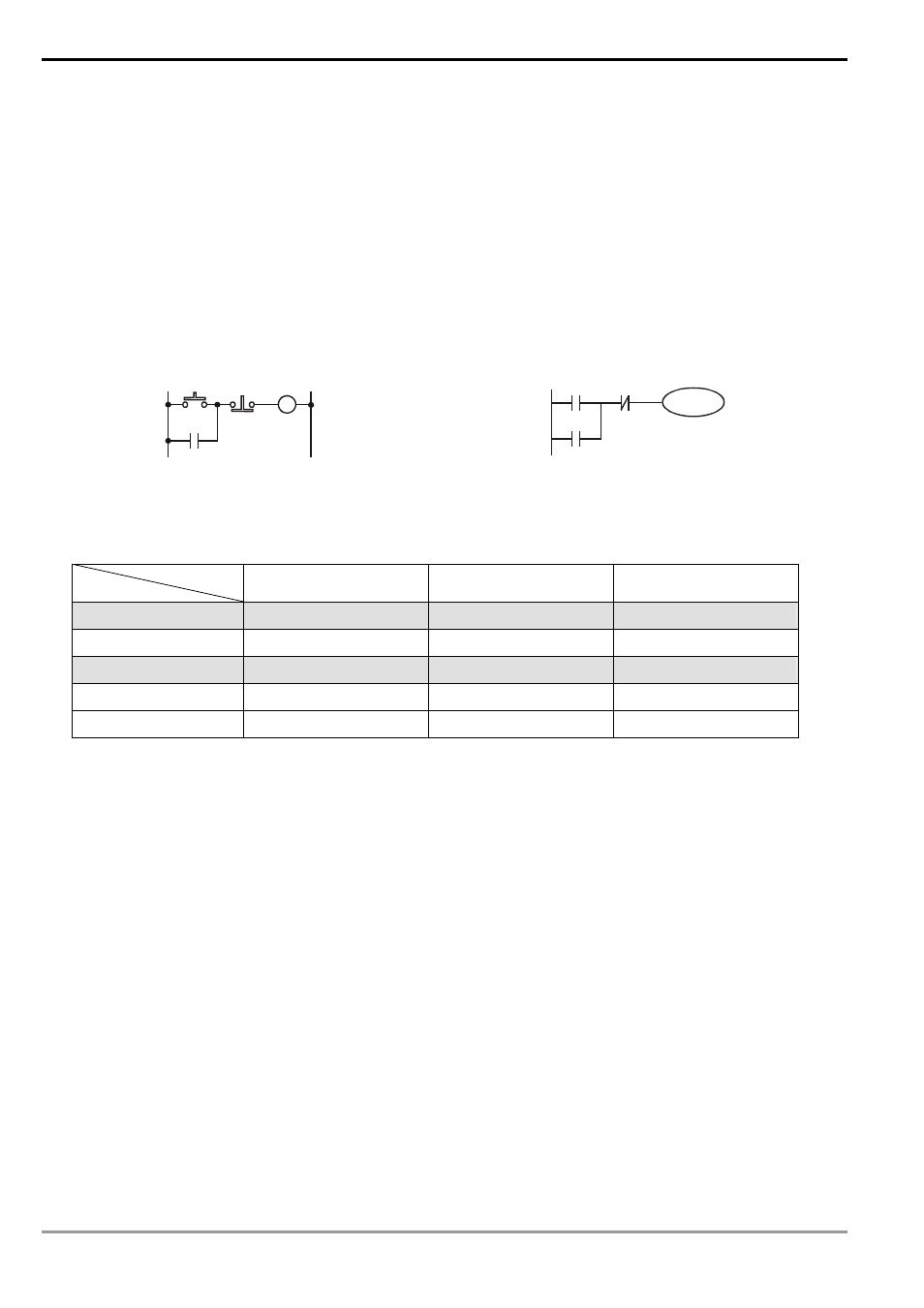
Row 2: Using a normally closed (NC) switch X1 (“B” switch or “B” contact). When X1 is not pressed, the contact
will be On, so Y1 will be On. When X1 is pressed, the contact will be open loop (Off), so Y1 will be Off.
Row 3: The combination logic of more than one input devices. Output Y2 will be On when X2 is not pressed or
X3 and X4 are pressed.
2. Sequential
Logic
Sequential logic is a circuit with "draw back” structure, i.e. the output result of the circuit will be drawn back as an
input criterion. Therefore, under the same input criteria, different previous status or action sequence will follow by
different output results.
Examples of traditional ladder diagram and PLC ladder diagram for sequential logic:
Traditional Ladder Diagram
PLC Ladder Diagram
Y3
X5
Y3
X6
Y3
X5
Y3
X6
When the circuit is first connected to the power, though X6 is On, X5 is Off, so Y3 will be Off. After X5 is pressed,
Y3 will be On. Once Y3 is On, even X5 is released (Off), Y3 can still keep its action because of the draw back (i.e.
the self-retained circuit). The actions are illustrated in the table below.
Device status
Action sequence
X5
X6
Y3
1
No action
No action
Off
2 Action
No
action
On
3
No action
No action
On
4 No
action
Action Off
5
No action
No action
Off
From the table above, we can see that in different sequence, the same input status can result in different output
results. For example, switch X5 and X6 of action sequence 1 and 3 do not act, but Y3 is Off in sequence 1 and
On in sequence 3. Y3 output status will then be drawn back as input (the so-called “draw back”), making the
circuit being able to perform sequential control, which is the main feature of the ladder diagram circuit. Here we
only explain contact A, contact B and the output coil. Other devices are applicable to the same method. See
Chapter 3 “Basic instructions” for more details.
1.2 Differences Between Traditional Ladder Diagram and PLC Ladder Diagram
Though the principles of traditional ladder diagram and PLC ladder diagram are the same, in fact, PLC adopts
microcomputer to simulate the motions of the traditional ladder diagram, i.e. scan-check status of all the input devices
and output coil and calculate to generate the same output results as those from the traditional ladder diagram based
on the logics of the ladder diagram. Due to that there is only one microcomputer, we can only check the program of
the ladder diagram one by one and calculate the output results according to the program and the I/O status before the
cyclic process of sending the results to the output interface Æ re-reading of the input status Æ calculation Æ output.
The time spent in the cyclic process is called the “scan time” and the time can be longer with the expansion of the
program. The scan time can cause delay from the input detection to output response of the PLC. The longer the delay,