Dvp-plc application manual – Delta Electronics Programmable Logic Controller DVP-PLC User Manual
Page 509
9 Application Instructions API 150-199
DVP-PLC Application Manual
9-37
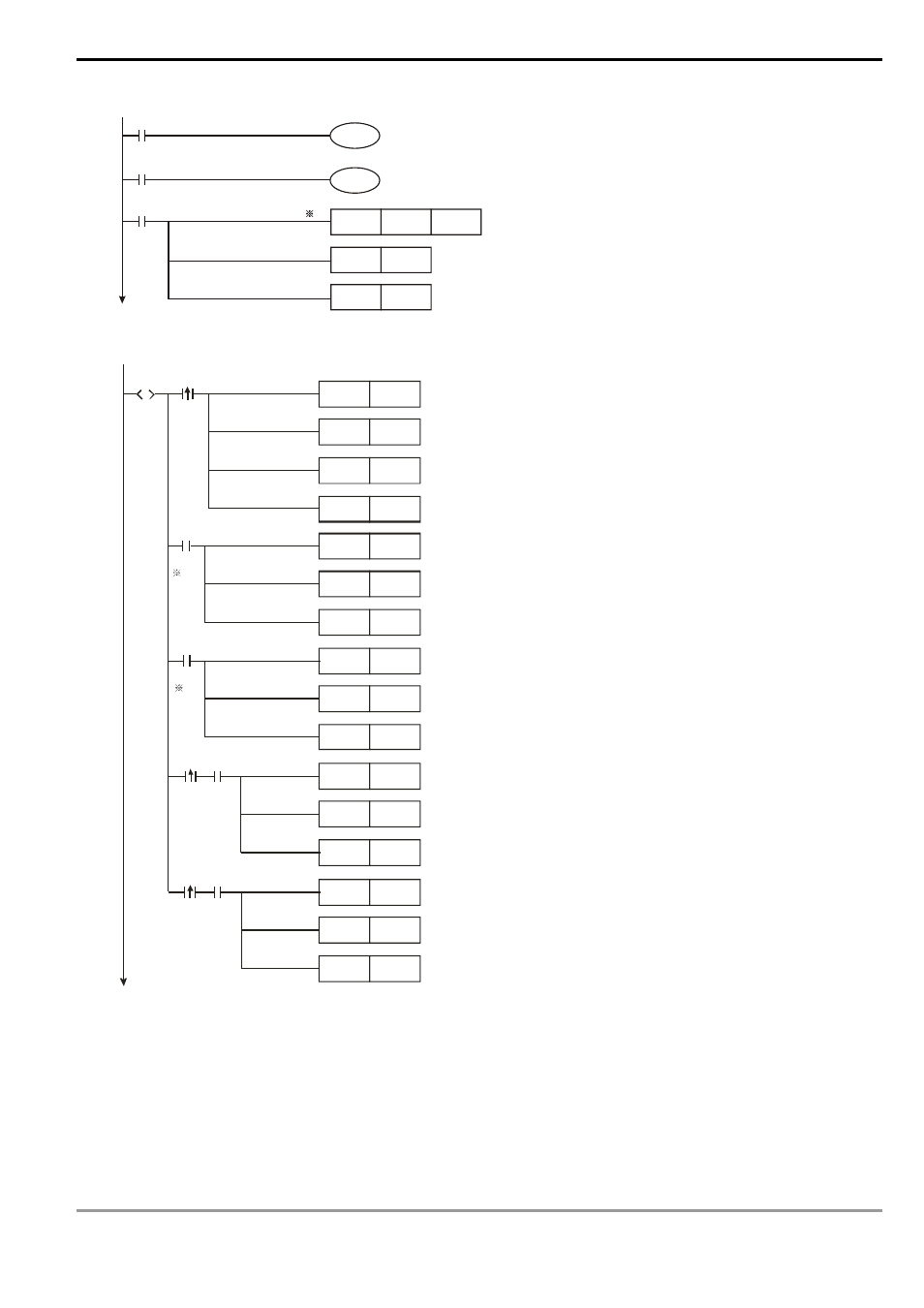
11. Programming example of using step ladder instruction (STL):
M1002
M1000
X4
1
200ms--D1343
MOV
K200
D1343
M1334
M1346
SET
S0
SET
Y5
SERVO On control
Stop
Y0 pulse output pauses
With clear signal output
Valid zero return
Settings of accel/decel time
※1.
If the accel./decel. time (D1343) of CH1 can be default setting, (100ms) this program step can be ignored.
X7
RS T
M1 0
RS T
M1 2
RS T
M1 3
S ET
S 20
X10
RS T
M1 2
RS T
M1 3
S ET
S 21
X11
RS T
M1 2
RS T
M1 3
S ET
S 22
X12
RS T
M1 2
RS T
M1 3
S ET
S 23
M10
X13
RS T
M1 2
RS T
M1 3
S ET
S 24
M10
2
2
S
S0
JOG (+)
Zero
return
JOG (-)
For war d
Positioning
Backward
Positioning
Zero
return
completed
flag
Zero
return
completed
flag
Reset zero point return completed flag
Reset forward positioning completed flag
Reset backward positioning completed flag
Drive zero return (S20)
Reset forward positioning completed flag
Reset backward positioning completed flag
Drive JOG(+) (S21 )
Reset forward positioning completed flag
Reset backward positioning completed flag
Drive JOG(-) (S22)
Reset forward positioning completed flag
Reset backward positioning completed flag
Drive forward positioning (S23)
Reset forward positioning completed flag
Reset backward positioning completed flag
Drive backward positioning (S24)
※2.
The max. traveling distance of a JOG operation equals to the max. number of output pulses
(-2,147,483,648 ~ +2,147,483,647) of API 158 DDRVI instruction. Please re-execute JOG of the traveling
distance exceeds the range.