Delta Electronics CANopen Communication Module DVPCOPM-SL User Manual
Delta Electronics Hardware
Warning
Please read this instruction sheet carefully before use and follow the sheet to operate DVPCOPM-SL in order
to prevent damages on the device or injuries to staff.
Switch of the power when wiring. DO NOT touch any terminal when the power is switched on.
This instruction sheet only provides introductory information on electrical specifications, functions, wiring,
trouble-shooting and peripherals for DVPCOPM-SL. Details of CANopen protocol are not included in this
sheet. For more information on CANopen, please refer to relevant reference or literatures.
DVPCOPM-SL is an OPEN-TYPE device and therefore should be installed in an enclosure free of airborne
dust, humidity, electric shock and vibration. The enclosure should prevent non-maintenance staff from
operating the device (e.g. key or specific tools are required to open the enclosure) in case danger and
da mages on the device may occur.
DO NOT connect input AC power supply to any of the I/O terminals; otherwise serious damage may occur.
Check all the wiring again before switching on the power and DO NOT touch any terminal when the power is
switched on. Make sure the ground terminal
is correctly grounded in order to prevent electromagnetic
interference.
Introduction
Functions
1. Complied with CANopen standard protocol
DS301v4.02
2. Supports NMT service
3. Supports Error Control Protocol
4. Supports SDO service
5. Supports EDS files in
CANopen Configurator
6. Supports PDO service:
Supports max. 200 RxPDOs and the data can be
up to 390 bytes.
Supports max. 200 TxPDOs and the data can be
up to 390 bytes.
7. PDO transmission type: supports event trigger,
time trigger, synchronous cycle and synchronous
non-cycle.
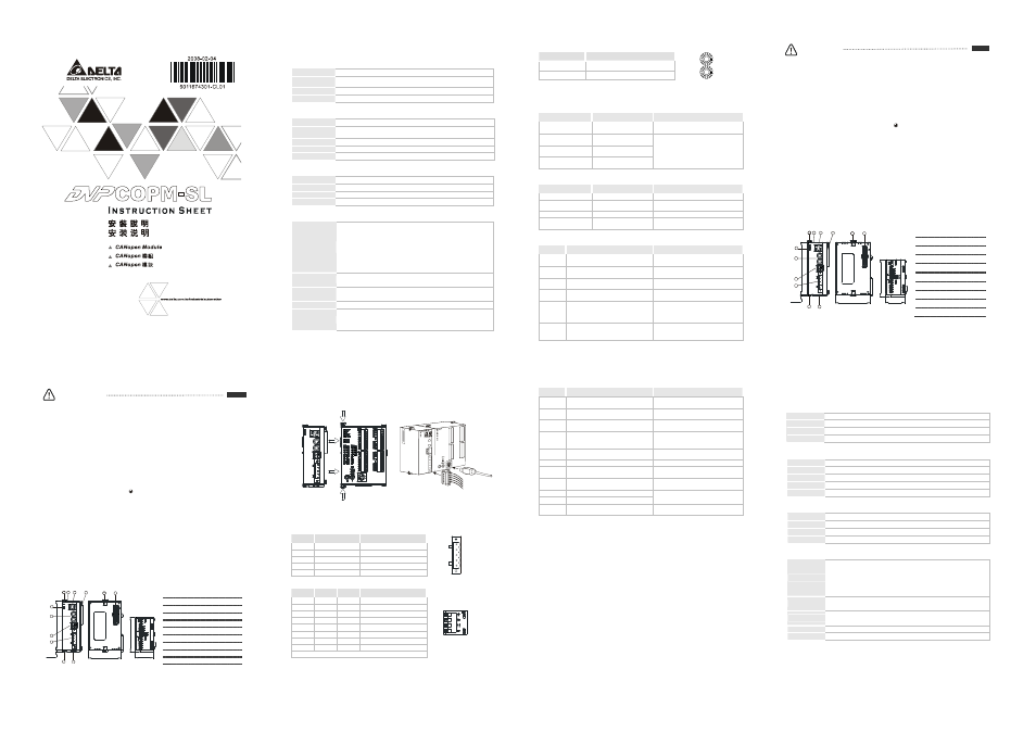
Product Profile & Outline
3
4
7
5
8
2
9
6
6
6
1
2
9
0
[3
.5
4
3
]
60 [2.362]
6
3
.4
[2
.4
9
6
]
33 .1 [1.303]
3 [0.118 ]
IN 0
SHLD
GND
CAN-
DVPCOPM
ERR
N
O
D
E
A
D
D
R
E
S
S
0
DR 2
DR 1
DR 0
x1 6
x1 6
1
POWER
RUN
Unit: mm and [inch]
1 Model name
2 Connection port for extension unit
3 Power, Run, Error indicators
4 DIN rail clip
5 Digital display
6 Fixing clip for extension unit
7 Address setup rotary switch
8 Function setup DIP switch
9 CANopen connector
ENGLISH
Specifications
CANopen Connector
Type
Removable connector (5.08mm)
Transmission
method
CAN
Transmission cable
2 communication cables, 1 shielded cable and 1 grounding cable
Electrical isolation
500V DC
Communication
Message type
PDO, SDO, SYNC (synchronous object), Emergency (emergency object), NMT
Series transmission
speed
10K, 20K, 50K,125K, 250K, 500K, 800K, 1M bps (bits per second)
Product code
64
Equipment type
0 (Non-Profile)
Company ID
477 (Delta Electronics, Inc.)
Electrical Specifications
Power voltage
24V DC (-15% ~ 20%) (supplied by the internal bus from MPU)
Power consumption
1.7 W
Isolation voltage
500 V
Weight (approx. g)
66 (g)
Environment
Interference
immunity
ESD (IEC 61131-2, IEC 61000-4-2): 8KV Air Discharge, 4KV Contact
Discharge
EFT (IEC 61131-2, IEC 61000-4-4): Power Line: 2KV, Digital I/O: 1KV
Analog & Communication I/O: 1KV
Damped-Oscillatory Wave: Power Line: 1KV, Digital I/O: 1KV
RS (IEC 61131-2, IEC 61000-4-3): 80MHz ~ 1000MHz , 1.4GHz ~ 2.0GHz ,
10V/m
Operation/Storage
Operation: 0ºC ~ 55ºC (temperature), 50 ~ 95% (humidity), pollution degree 2
Storage: -25ºC ~ 70ºC (temperature), 5 ~ 95% (humidity)
Shock/vibration
immunity
International standards: IEC 61131-2, IEC 68-2-6 (TEST Fc)/IEC 61131-2 &
IEC 68-2-27 (TEST Ea)
Certificates
IEC 61131-2, UL508
Configuration
DVPCOPM-SL modules are numbered automatically from 1 ~ 8 according to
their distance from the MPU (1 is the closest one). Maximum 8 modules are
extendable
Installation
Connecting DVPCOPM-SL with SV series MPU
DVP28SV
G ND
S HLD
CAN -
N
O
D
E
A
D
D
R
E
S
S
DR 1
IN 0
DR 0
DR 2
x16
0
x16
1
ER R
R U N
PO W ER
DVPC OPM
Components
CANopen Connector
PIN
Signal
Description
1
GND
GND
2
CAN_L
Signal-
3
SHLD
Shielded cable
4
CAN_H
Signal+
5
-
Reserved
4
GN D
S H L D
C A N-
C AN +
5
3
2
1
Function Setup DIP Switch
DR2
DR1
DR0
Baud Rate
OFF
OFF
OFF
10K bps
OFF
OFF
ON
20K bps
OFF
ON
OFF
50K bps
OFF
ON
ON
125K bps
ON
OFF
OFF
250K bps
ON
OFF
ON
500K bps
ON
ON
OFF
800K bps
ON
ON
ON
1M bps
IN 0
DR 1
IN 0
DR 0
DR 2
Note:
The setup of address and function is only valid when the power of DVPCOPM-SL is switched off.
Re-power the module after the setup is completed.
Address Setup Rotary Switch
Address Setting
Description
1 ~ 7F
Valid CANopen node address
0, 80 ~ FF
Invalid CANopen node address
N
O
D
E
A
D
D
R
E
S
S
x1 6
0
x1 6
1
LED Indicator & Trouble-shooting
RUN LED
LED Status
Indication
How to deal with it
Off
No power
Check the power of DVPCOPM-SL and
make sure the connection is normal.
Green light single flash
DVPCOPM-SL in STOP
status
Green light blinking
DVPCOPM-SL in
pre-operational status
Green light steady on
DVPCOPM-SL in operational
status
No action needed
ERROR LED
LED Status
Indication
How to deal with it
Off
Normal
No action needed
Red light single flash
Bus error exceeds the
warning limit
Check if the network connection and
operation are normal.
Red light double flash
Error control event
See the indication from digital display.
Red light steady on
Bus-off
Check if the Bus connection is normal and
re-power DVPCOPM-SL
Codes in Digital Display
Code
Indication
How to deal with it
0 ~ 7F
The node address of DVPCOPM-SL when
in normal operation.
No action needed
F1
No slaves configured in node list
Re-configured the node list and download it
to DVPCOPM-SL
F2
The data are being downloaded to
DVPCOPM-SL
No action needed
F3
DVPCOPM-SL in error status
Check if the wiring of DVPCOPM-SL is
correct.
F4
Bus-off is detected
Make sure the communication cable is in
normal operation and all the nodes in the
network work in the same baud rate.
Re-power DVPCOPM-SL.
F5
Incorrect DVPCOPM-SL settings
Check the settings of node address and
baud rate and make sure the settings are
correct.
Code
Indication
How to deal with it
F6 ~ F8
Internal (device, GPIO check, memory)
abnormality is detected.
Re-power DVPCOPM-SL. If the error still
exists, change to a new DVPCOPM-SL
F9
Low voltage is detected.
Check and make sure the power of
DVPCOPM-SL works normally.
E0
DVPCOPM-SL receives Emergency
message sent by the Slave.
Read relevant information through PLC
MPU.
E1
PDO data length returning from the Slave is
not consistent with the length set in the
Slave address
Reset the PDO data length in the Slave and
download the new setting to DVPCOPM-SL
E2
PDO message from the Slave has not been
received.
Check and make sure the setting is correct.
E3
Auto SDO download failed.
Check and make sure Auto SDO is correct.
E4
PDO parameter setting has failed.
Make sure the PDO parameter setting is
legal.
E5
Error in key parameter setting
Make sure all the Slaves connected are
consistent with the Slaves set.
E6
The Slave does not exist in the network.
E7
Slave’s Error control is time-out
Make sure the power of the Slave and the
network connection work normally.
E8
Master/slave node address is repeated
Reset the node address and make sure the
new node address is not repeated one.
注意事項
使用前請務必仔細閱讀本使用手册,並按照本手册指示進行操作,以免造成産品受損或人員受傷。
配線時請務必關閉電源,當模組上電後,請勿觸摸接線端子。
此安裝手册只提供電氣規格、一般規格、安裝配線、故障排除及周邊裝置部分說明,本說明書僅作爲
DVPCOPM-SL
操作指南和入門參考,CANopen 協定之詳細內容這裏不作介紹。如讀者想瞭解更多
CANopen
協定之內容,請參閱相關專業文章或書籍資料。
本機爲開放型(Open Type)機殼,因此使用者使用本機時,必須將其安裝於具防塵、防潮及免於電擊
/
衝擊意外之外殼配線箱內。另必須具備保護措施(如:特殊之工具或鑰匙才可打開),防止非維護人員
操作或意外衝擊本體,造成危險及損壞。
交流輸入電源不可連接於輸入/輸出訊號端,否則可能造成嚴重損壞。請在上電前再次確認電源配線,
且請勿在上電時觸摸任何端子。本體上的接地端子 務必正確的接地,以提高産品抗雜訊能力。
產品簡介
功能
1.
符合 CANopen 標準協定 DS301v4.02
2.
支援 NMT 服務
3.
支援 Error Control Protocol
4.
支援 SDO 服務
5.
在 CANopen 組態軟體中支援 EDS 檔案配置
6.
支援 PDO 服務:
RxPDO
最大支援 200 個,資料量最大支援 390 個
位元組。
TxPDO
最大支援 200 個,資料量最大支援 390 個
位元組。
7. PDO
傳輸類型:支援事件觸發、時間觸發、同步週
期、同步非週期。
産品外觀
3
4
7
5
8
2
9
6
6
6
1
2
9
0
[3
.5
4
3
]
60 [2.362]
63
.4
[2
.4
9
6
]
33.1 [1.303]
3 [0.118]
IN 0
SHL D
GND
CAN-
DV PCOPM
ER R
N
O
D
E
A
D
D
R
E
S
S
0
DR 2
DR 1
DR 0
x 16
x 16
1
PO WER
RU N
尺寸單位:mm 和 [inch]
1
機種名稱
2
擴充機連接口
3 Power
、Run、Error 指示燈
4 DIN
軌固定扣
5
數位顯示器
6
擴充機固定扣
7
位址設定開關
8
功能設定開關
9 CANopen
通訊連接器
繁體中文
功能規格
CANopen
連接器
接頭
可插拔式連接器 (5.08mm)
傳輸方式
CAN
傳輸電纜
兩條通訊線、一條遮蔽線和一條接地線
電氣隔離
500V DC
通訊
資訊類型
PDO
、SDO、SYNC(同步物件)、Emergency(緊急物件)、NMT
串列傳輸速度
支援 10K、20K、50K、125K、250K、500K、800K、1M bps(位元/秒)
産品代碼
64
設備類型
0
(Non-Profile)
廠商 ID
477
(台達電子)
電氣規格
電源電壓
由主機經由內部匯流排供應 24VDC (-15% ~ 20%)
消耗電力
1.7 W
絕緣電壓
500 V
重 量 (約,g)
66 (g)
環境規格
雜訊免疫力
ESD (IEC 61131-2, IEC 61000-4-2): 8KV Air Discharge, 4KV Contact Discharge
EFT (IEC 61131-2, IEC 61000-4-4): Power Line: 2KV, Digital I/O: 1KV
Analog & Communication I/O: 1KV
Damped-Oscillatory Wave: Power Line: 1KV, Digital I/O: 1KV
RS (IEC 61131-2, IEC 61000-4-3): 80MHz ~ 1000MHz , 1.4GHz ~ 2.0GHz , 10V/m
操作/儲存環境
操作:0ºC ~ 55ºC(溫度)、50 ~ 95%(濕度)、污染等級 2
儲存:-25ºC ~ 70ºC(溫度)、5 ~ 95%(濕度)
耐震動/衝擊
國際標準規範 IEC 61131-2、IEC 68-2-6 (TEST Fc)/IEC 61131-2 & IEC 68-2-27 (TEST
Ea)
標準
IEC 61131-2
、UL508 標準
配置
DVPCOPM-SL
左側模組編號以靠近主機之順序自動編號由 1 ~ 8,最大可連接 8 台。