Delta Electronics Programmable Logic Controller DVP-PLC User Manual
Page 375
7 Application Instructions API 50-99
D V P - P L C A P P L I C AT I O N M A N U A L
7-91
06H: Write 1 word to register
10H: Write in contents of many registers
Data characters: The data sent by the user.
CRC checksum: Starting from Address and ending at Data Content.
Step 1: Make the 16-bit register (CRC register) = FFFFH
Step 2: Exclusive OR the first 8-bit message and the low 16-bit CRC register. Store the result in the CRC
register.
Step 3: Right shift CRC register for a bit and fill “0” into the high bit.
Step 4: Check the value shifted to the right. If it is 0, fill in the new value obtained in step 3 and store the value
in CRC register; otherwise, Exclusive OR A001H and CRC register and store the result in the CRC
register.
Step 5: Repeat step 3 – 4 and finish operations of all the 8 bits.
Step 6: Repeat step 2 – 5 for obtaining the next 8-bit message until the operation of all the messages are
completed. The final value obtained in the CRC register is the CRC checksum. The CRC checksum
has to be placed interchangeably in the checksum of the message.
END:
For ES/EX/SS V5.8 (and below) and SA/SX V1.1 (and below) series MPU, keep no input signal be ≥ 10ms.
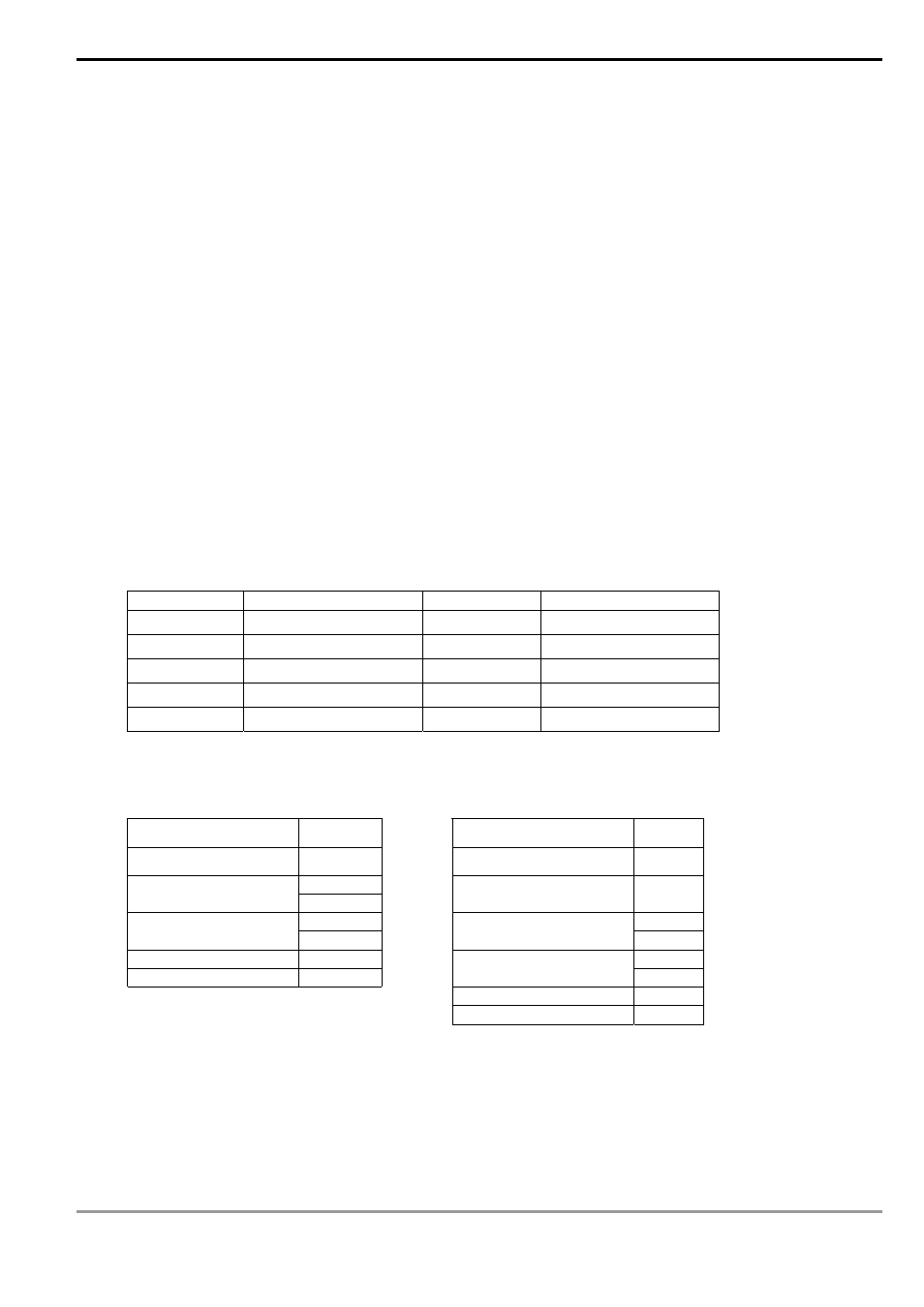
See the table below for EH/EH2/SV series MPU:
Baud rate(bps) RTU timeout timer (ms) Baud rate (bps) RTU timeout timer (ms)
300 40 9,600 2
600 21
19,200 1
1,200 10 38,400 1
2,400 5 57,600 1
4,800 3 115,200 1
For example: Read 2 continuous data stored in the registers of the driver at address 01H (see the table below).
The start register is at address 2102H.
Inquiry message:
Responding message:
Address 01
H
Address 01
H
Function 03
H
Function 03
H
21 H
Start data address
02 H
Number of data
(counted by byte)
04 H
00 H
17 H
Number of data
(counted by words)
02 H
Content in data address
8102H
70 H
CRC CHK Low
6F H
00 H
CRC CHK High
F7 H
Content in data address
8103H
00 H
CRC CHK Low
FE H
CRC CHK High
5C H