Delta Electronics Programmable Logic Controller DVP-PLC User Manual
Page 422
8 Application Instructions API 100-149
DVP-PLC Application Manual
8-20
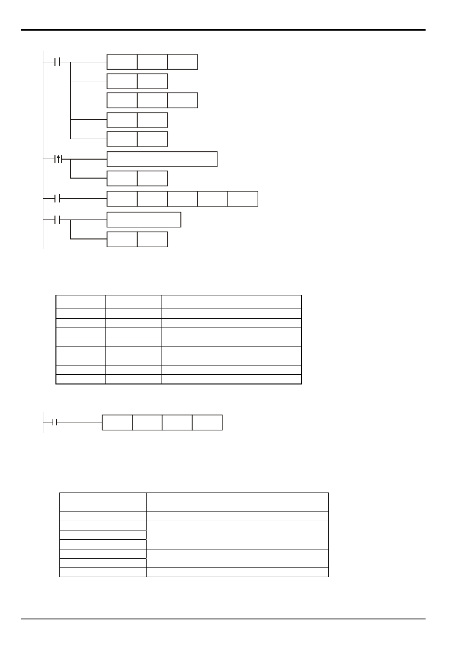
M1002
X10
M1123
RST
M1123
RS
D100
K8
D120
K8
SET
M1143
SET
M1161
RTU
Mode
8-
bit Mode
Write transmitting data in advance
transmission
request
pulse
Receiving completed and flag reset
MOV
D1120
H87
SET
M1120
MOV
D1129
K100
Set up communication protocol
to 9600, 8, E, 1
Retain communication protocol
Set up communication
time-out: 100ms
SET
M1122
Set up transmission request
receiving completed
Process received data
PLC VFD-S, PLC sends: 01 06 2000 0012 02 07
Registers for sent data (sending messages)
Register DATA
Explanation
D100 low
01 H
Address
D101 low
06 H
Function
D102 low
20 H
D103 low
00 H
Data address
D104 low
00 H
D105 low
12 H
Data content
D106 low
02 H
CRC CHK 0
D107 low
07 H
CRC CHK 1
The error checksum CRC CHK (0,1) can be calculated by CRC instruction (in 8-bit mode, M1161 = On).
M1000
CRC
D100
K6
D106
CRC checksum: 02 H is stored in the lower 8 bits of D106 and 07 H in the lower 8 bits of D107,
Remarks:
1. The format of RTU mode with a communication datum
START Time
interval
Address
Communication address: 8-bit binary
Function
Function code: 8-bit binary
DATA (n-1)
…….
DATA 0
Data content:
n × 8-bit data
CRC CHK Low
CRC CHK High
CRC checksum:
16-bit CRC checksum consists of 2 8-bit binaries
END Time
interval
2. CRC checksum starts from Address and ends at Data content.