3 how does a step ladder instruction work, 4 step ladder instructions – Delta Electronics Programmable Logic Controller DVP-PLC User Manual
Page 173
4 Step Ladder Instructions
DVP-PLC Application Manual
4-3
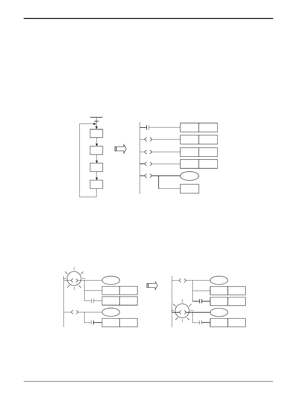
4.3 How does a Step Ladder Instruction Work?
STL instruction is used for designing the syntax of a sequential function chart (SFC), making the program
designing similar to drawing a flow chart and allowing a more explicit and readable program. From the figure in the left
hand side below, we can see very clearly the sequence to be designed, and we can convert the sequence into the
step ladder diagram in the right hand side.
RET instruction has to be written at the end of every step sequence, representing the end of a sequence. There
can be more than one step sequence in a program. Therefore, we have to write in RET at the end of every step
sequence. There is no limitation on the times of using RET which is used together with S0 ~ S9.
If there is no RET instruction at the end of a step sequence, errors will be detected by WPL editor.
S0
S21
S22
S23
M1002
S0
SET
SET
S22
S0
RET
S21
S
S22
S
SET
S21
S0
S
S23
S
SET
S23
M1002
initial pulse
1. Actions of Step Ladder:
A step ladder is composed of many steps and every step controls an action in the sequence. The step ladder
has to:
a) Drive the output coil
b) Designate the transition condition
c) Designate which step will take over the control from the current step
Example:
SET
Y1
Y0
SET
S20
Y10
SET
S30
S10
S
X0
S20
S
X1
SET
Y1
Y0
SET
S20
Y10
SET
S30
S10
S
X0
S20
S
X1
When X0=On,
S20 = On,
S10 = Off.
Explanation:
When S10 = On, Y0 and Y1 will be On. When X0 = On, S20 will be On and Y10 will be On. When S10 = Off, Y0
will be Off and Y1 will be On.
2. Timing Diagram of Step Ladder: