Delta Electronics Programmable Logic Controller DVP-PLC User Manual
Page 414
8 Application Instructions API 100-149
DVP-PLC Application Manual
8-12
400.0Hz). Set frequency in H-series: K0 ~ K1,500 (0Hz ~ 1,500Hz).
8. n = instructed target. n=1: AC motor drive at designated address. n=2: all connected AC motor drives.
9. The feedback (returned) data from the peripheral equipment will be stored in D1070 ~ D1080. After receiving
the feedback data is completed, PLC will auto-check if all data are correct. If there is an error, M1142 will be On.
When n = 2, PLC will not receive any data.
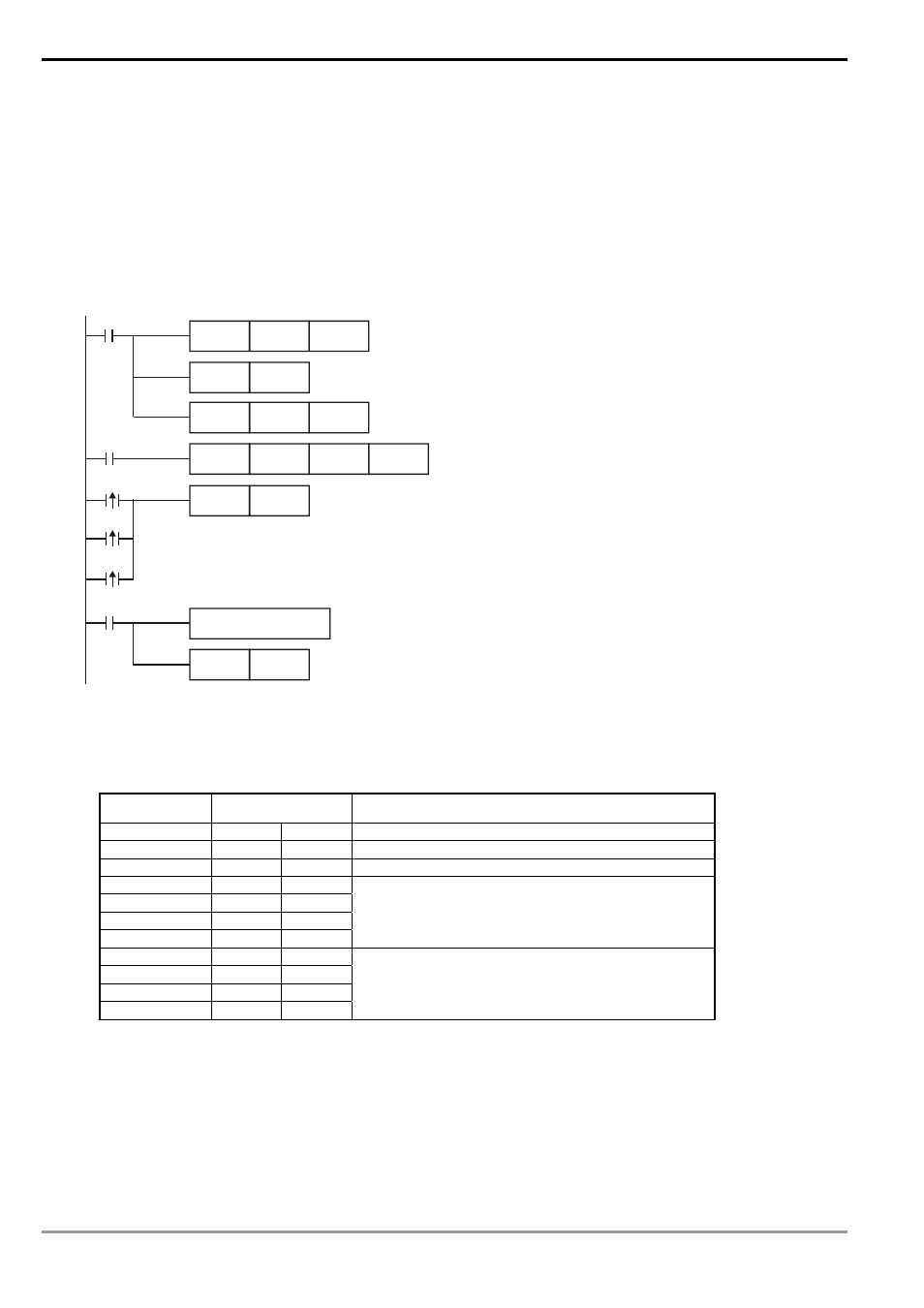
Program Example :
Communication between PLC and VFD-A series AC drives, retry for communication time-out and received data error.
M1002
MOV
H0073
D1120
SET
M1120
MOV
K100
D1129
RST
M1127
M1127
X0
FWD
K0
K500
K1
SET
M1122
M1129
M1142
X0
Communication time-out Retry
Data receive error Retry
handle received data
Receiving completed
Communication command setting:Device address: 0
Frequency: 500Hz K1: indicated AC motor drive
Set up communication protocol to 4800, 8, O, 1
Retain communication protocol
Set up communication time-out: 100ms
Set up transmission request
Sending/receiving of data is completed. The flag is reset.
The received data are stored in the low bit group of
D1070 ~ D1080 by ASCI format.
PLC VFD-A, PLC sends: “C ♥ ☺ 0001 0500 ”
VFD-A PLC, PLC sends: “C ♥ ♠ 0001 0500 ”
Registers for sent data (sending messages)
Register DATA
Explanation
D1089 low
‘C’
43 H
Start word of instruction
D1090 low
‘♥’ 03
H
Checksum
D1091 low
‘☺’
01 H
Instructed target
D1092 low
‘0’
30 H
D1093 low
‘0’
30 H
D1094 low
‘0’
30 H
D1095 low
‘1’
31 H
Communication address
D1096 low
‘0’
30 H
D1097 low
‘5’
35 H
D1098 low
‘0’
30 H
D1099 low
‘0’
30 H
Running instruction