6 simplified ladder diagram, 1 basic principles of plc ladder diagram – Delta Electronics Programmable Logic Controller DVP-PLC User Manual
Page 19
1 Basic Principles of PLC Ladder Diagram
DVP-PLC Application Manual
1-15
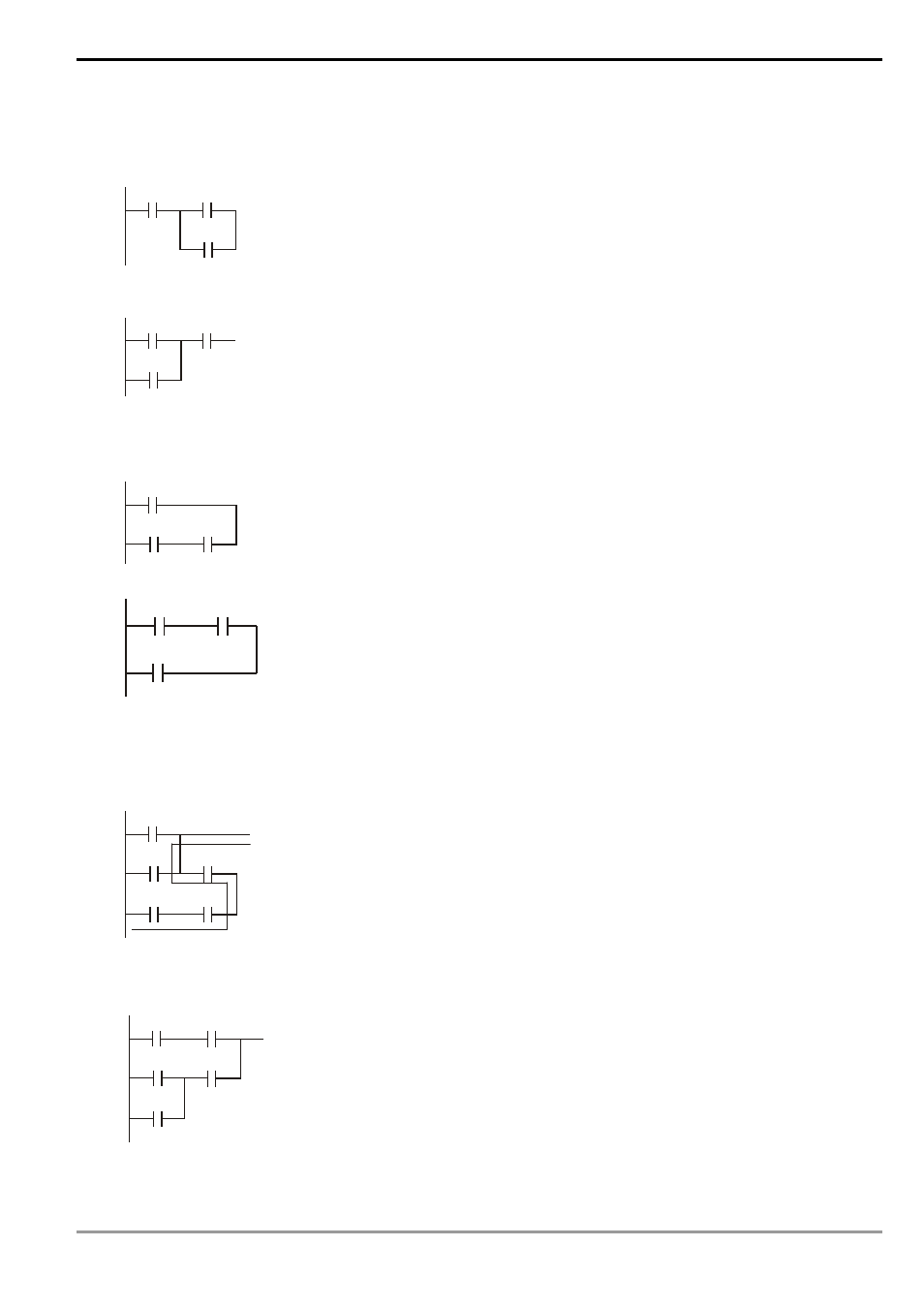
1.6 Simplified Ladder Diagram
When a series block is connected to a parallel block in series, place the block in the front to omit ANB instruction.
Ladder diagram complied into instruction
LD X0
LD X1
OR X2
X0
X1
X2
Ø
ANB
Ladder diagram complied into instruction
LD X1
OR X2
X0
X1
X2
AND X0
When a single device is connected to a block in parallel, place the block on top to omit ORB instruction.
Ladder diagram complied into instruction
LD T0
LD X1
AND X2
T0
X1
X2
Ø
ORB
Ladder diagram complied into instruction
LD X1
AND X2
T0
X1
X2
OR T0
In diagram (a), the block on top is shorter than the block in the bottom, we can switch the position of the two
blocks to achieve the same logic. Due to that diagram (a) is illegal, there is a “reverse flow” in it.
Ladder diagram complied into instruction
LD X0
OR X1
AND X2
LD X3
AND X4
X0
X1
X2
X3
X4
(a)
Ø
ORB
Ladder diagram complied into instruction
LD X3
AND X4
LD X1
OR X0
AND X2
X0
X1
X2
X3
X4
(b)
ORB