Delta Electronics Programmable Logic Controller DVP-PLC User Manual
Page 571
9 Application Instructions API 150-199
DVP-PLC Application Manual
9-99
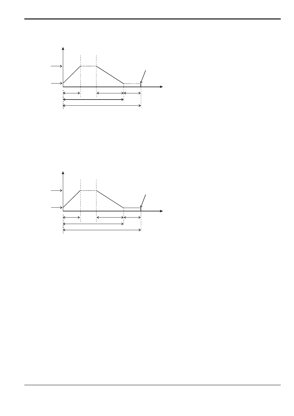
3. Assume the first execution result as:
100KHz
D1340
D1348
D1343
C251 =K50000
3s
Frequency
Y0 stops output
Time
Number
Estimated number of output pulses: 50,000
Actual number of output pulses (D1336, D1337) = K50,600
4. Observe the result of the first execution:
a) The actual output number 50,600 – estimated output number 50,000 = 600
b) 600 x (1/200Hz) = 3s (idling time)
c) 3 seconds are too long. Therefore, increase the percentage value (D1198) to K101.
5. Obatin the result of the second execution:
100KHz
D1340
D1348
D1343
C251 =K50000
300ms
Frequency
Y0 stops output
Time
Number
Estimated number of output pulses: 50,500
Actual number of output pulses (D1336, D1337) = K50,560
6. Observe the result of the second execution:
a) The actual output number 50,560 – estimated output number 50,500 = 60
b) 60 x (1/200Hz) = 300ms (idling time)
c) 300ms is an appropriate value. Therefore, set the percentage value (D1198) as K101 to complete the
design.
Remarks:
1. Flag
explanations:
M1010:
When On, CH0, CH1, CH2 and CH3 will output pulses when encountering END instruction. Off
when the output starts.
M1029:
On when CH0 pulse output is completed.
M1030:
On when CH1 pulse output is completed.
M1036:
On when CH2 pulse output is completed.
M1037:
On when CH3 pulse output is completed.
M1334:
When On, CH0 pulse output will be forbidden.
M1335:
When On, CH1 pulse output will be forbidden.