4 step ladder instructions – Delta Electronics Programmable Logic Controller DVP-PLC User Manual
Page 189
4 Step Ladder Instructions
DVP-PLC Application Manual
4-19
X15
X16
X17
X20
X21
X22
X23
X24
X25
Step X12
One cycle
Operation X13
Continuous
Operation X14
Manual
Operation X10
Zero Return X11
Start Power
Stop Power
Start Zero Return
Auto Start
Auto Stop
Right
Shift
Left
Shift
Release
Ball
Clip
Ball
Descend
Ascend
a) Ball size sensor X0.
b) Robot arm: left limit X1, big ball right limit X2, small ball right limit X3, upper limit X4, lower limit X5.
c) Robot arm: ascending Y0, descending Y1, right shifting Y2, left shifting Y3, clipping Y4.
Start Circuit
M1000
IST
X10
S20
S80
X0
M1044
X1
Y4
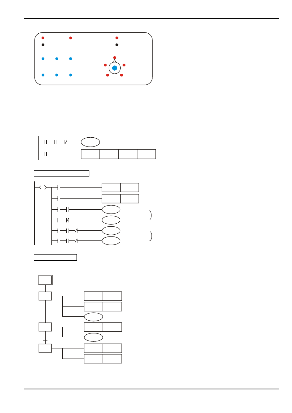
Manual Operation Mode
X20
SET
RST
Y4
Y4
S
S0
X21
X22 Y1
Y0
X23 Y0
Y1
X24 X4
Y2
Y3
X25 X4
Y3
Y2
Clipping tightly
Clipping released
Descending
Ascending
Interlocked
Right shifting
Left shifting
Interlocked
Robot arm ascends to upper limit (X4 On)
Zero Return Mode
SFC:
S1
S10
X15
S11
X4
S12
X1
RST
Y4
RST
Y1
Y0
RST
Y2
Y3
SET
M1043
RST
S12
Clipping released
Descending stops
Robot arm ascends to upper limit (X4 On)
Right shifting stops
Robot arm left shifting to left limit (X1 On)
Enable zero return completed flag
Zero return operation completed