2 functions of devices in dvp-plc – Delta Electronics Programmable Logic Controller DVP-PLC User Manual
Page 82
2 Functions of Devices in DVP-PLC
DVP-PLC Application Manual
2-54
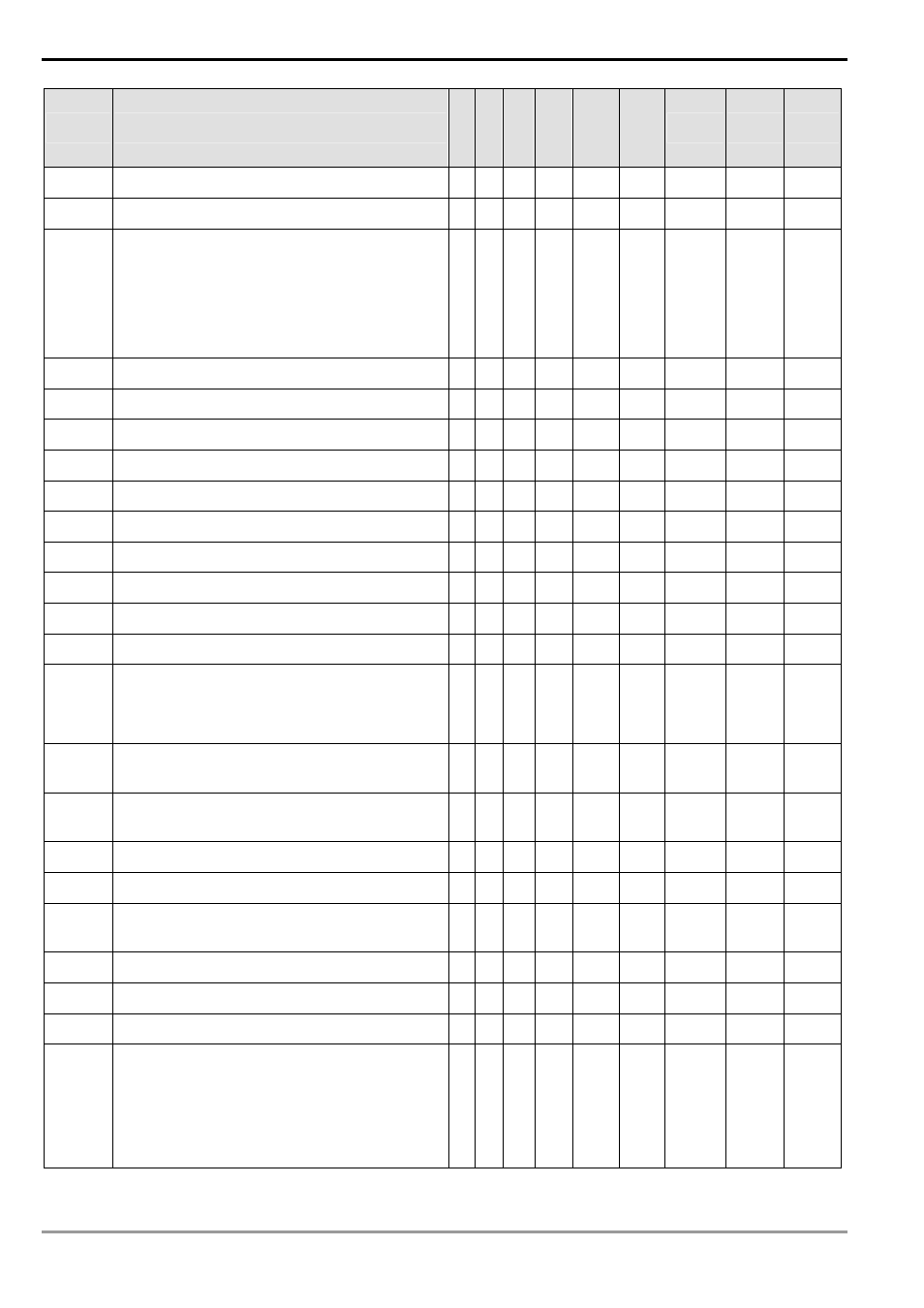
Special D
Function
ES
EX
SS
SA
SX
SC
EH
EH2
SV
Off
Ø
On
STOP
Ø
RUN
RUN
Ø
STOP
Attribute Latched Default
D1036* COM1 communication protocol
○ ○
○ H’86
- - R/W NO
H’86
D1037
Repetition time of HKY key
╳
╳
○
- - - R/W NO 0
D1038*
Delay time of data response when PLC MPU as
slave in RS-485 communication, range: 0 ~ 10,000
(unit: 0.1ms)
SA/EH: delay time for sending the next
communication data in EASY EASY PLC LINK (unit
for SA/SX/SC: 1 scan cycle; EH/EH2/SV: 0.1ms)
○ ○
○
- - - R/W YES 0
D1039* Fixed scan time (ms)
○ ○
○
0 - - R/W NO 0
D1040
On status of step No. 1
╳
○
○
0 - - R NO 0
D1041
On status of step No. 2
╳
○
○
0 - - R NO 0
D1042
On status of step No. 3
╳
○
○
0 - - R NO 0
D1043
On status of step No. 4
╳
○
○
0 - - R NO 0
D1044
On status of step No. 5
╳
○
○
0 - - R NO 0
D1045
On status of step No. 6
╳
○
○
0 - - R NO 0
D1046
On status of step No. 7
╳
○
○
0 - - R NO 0
D1047
On status of step No. 8
╳
○
○
0 - - R NO 0
D1049
No. of alarm On
╳
○
○
0 - - R NO 0
D1050
↓
D1055
Process of data for Modbus communication
instruction. PLC automatically converts the ASCII
data in D1070 ~ D1085 in to hex data.
○ ○
○
0 - - R NO 0
D1056*
Present value at analog input channel CH0 in SX/EX
or at CH0 on AD card in EH/EH2
○ ○
○
0 - - R NO 0
D1057*
Present value at analog input channel CH1 in SX/EX
or at CH1 on AD card in EH/EH2
○ ○
○
0 - - R NO 0
D1058* Present value at analog input channel CH2 in EX
○
╳
╳
0 - - R NO 0
D1059* Present value at analog input channel CH3 in EX
○
╳
╳
0 - - R NO 0
D1061
System error message: number of errors recorded in
latched area
○
╳
╳
- - - R YES 0
D1062
Average times of AD0, AD1 in SX (2 ~ 4 times)
╳
○
╳
2 - - R/W NO 2
D1067* Error code for operational error
○ ○
○
0 0 - R NO 0
D1068* Locking the address of operational error
○ ○
○
0 - - R NO 0
D1070
↓
D1085
Process of data for Modbus communication
instruction. When the RS-485 communication
instruction built-in the PLC sent out is received, the
response messages will be stored in D1070 ~
D1085. You can view the response messages by
checking these registers.
○ ○
○
0 - - R NO 0