2 functions of devices in dvp-plc – Delta Electronics Programmable Logic Controller DVP-PLC User Manual
Page 49
2 Functions of Devices in DVP-PLC
DVP-PLC Application Manual
2-21
speed counter with a total bandwidth of 20KHz, can be used alone with a counting frequency of up to 10KHz. C241 ~
C254 are hardware high speed counter (HHSC). There are four HHSC in EH/EH2/SV series MPU, HHSC0 ~ 3. The
pulse input frequency of HHSC0 and HHSC1 can reach 200KHz and that of HHSC2 and HHSC3 can reach 20KHz (1
phase or A-B phase). The pulse input frequency of HHSC0 ~ 3 of 40EH2 series MPU can reach 200KHz, among
which:
C241, C246 and C251 share HHSC0
C242, C247 and C252 share HHSC1
C243, C248 and C253 share HHSC2
C244, C249 and C254 share HHSC3
1. Every HHSC can only be designated to one counter by DCNT instruction.
2. There are three counting modes in every HHSC (see the table below):
a) 1-phase 1 input refers to “pulse/direction” mode.
b) 1-phase 2 inputs refers to “clockwise/counterclockwise (CW/CCW)” mode.
c) 2-phase 2 inputs refers to “A-B phase” mode.
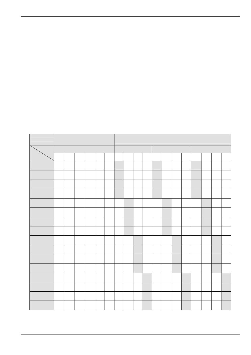
Counter type
Program-interruption
high speed counter
Hardware high speed counter
1-phase 1 input
1-phase 1 input
1-phase 2 inputs
2-phase 2 inputs
Type
Input
C235 C236 C237 C238 C239 C240 C241 C242 C243 C244 C246 C247 C248 C249 C251 C252 C253 C254
X0 U/D
U/D
U
A
X1
U/D
D
B
X2
U/D
R
R
R
X3
U/D
S
S
S
X4
U/D
U/D
U
A
X5
U/D
D
B
X6
R
R
R
X7
S
S
S
X10
U/D
U A
X11
D B
X12 R
R R
X13 S
S S
X14
U/D
U A
X15
D B
X16 R
R R
X17
S
S S
U: Progressively increasing input
A: A phase input
S: Input started
B: Progressively decreasing input
B: B phase input
R: Input cleared
3. System structure of the hardware high speed counters: