Delta Electronics Programmable Logic Controller DVP-PLC User Manual
Page 514
9 Application Instructions API 150-199
DVP-PLC Application Manual
9-42
API Mnemonic
Operands
Function
163
TSUB P
Time Subtraction
Controllers
ES/EX/SS SA/SX/SC EH/SV
Bit Devices
Word Devices
Program Steps
Type
OP
X Y M S K H
KnX
KnY KnM KnS T
C
D
E
F
S
1
*
*
*
S
2
*
*
*
D
*
*
*
TSUB, TSUBP: 7 steps
PULSE 16-bit 32-bit
ES EX SS SA SX SC EH SV ES EX SS SA SX SC EH SV ES EX SS SA SX SC EH SV
Operands:
S
1
: Time minuend S
2
: Time subtrahend D: Time remainder
Explanations:
1.
S
1
, S
2
, and D will occupy 3 consecutive devices.
2.
See the specifications of each model for their range of use.
3.
Flags: M1020 (zero flag); M1021 (borrow flag)
4.
S
1
− S
2
= D. The hour, minute, and second of the RTC designated in S
1
minus the hour, minute, and second
designated in S
2
. The result is stored in the hour, minute, and second of the register designated in D.
5. If
S
1
and S
2
exceed their ranges, the program will regard this as an operation error and the instruction will not
be executed. M1067 and M1068 will be On and D1067 record the error code 0E1A (hex).
6.
If the remainder is a negative value, the borrow flag M1021 will be On. The value in D will be the result of “the
negative value pluses 24 hours”.
7.
If the remainder equals 0 (00:00:00), the zero flag M1020 will be On.
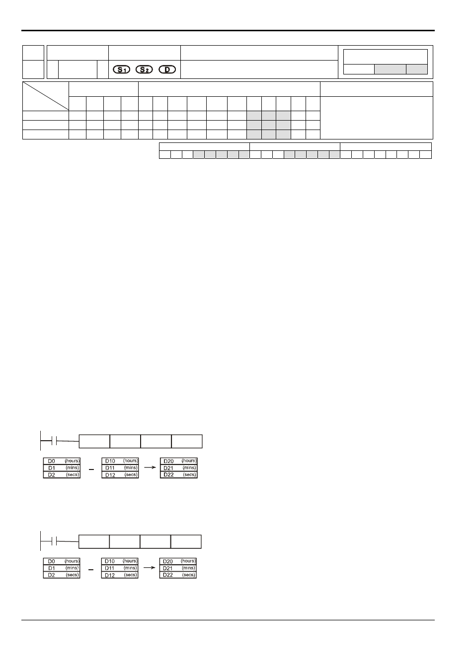
Program Example:
1.
When X10= On, TADD instruction will be executed and the hour, minute and second in RTC designated in D0
~ D2 will minus the hour, minute and second in RTC designated in D10 ~ D12. The remainder is stored in the
hour, minute and second of the register designated in D20 ~ D22.
X10
TSUB
D0
D10
D20
14
30
8
5
57
49
20
20:20:05
14:30:08
05:49:57
20
5
2.
If the subtraction result is a negative value, M1021 will be On.
X10
TSUB
D0
D10
D20
19
11
15
15
9
20
05:20:30
19:11:15
10:09:15
5
30
10