2 functions of devices in dvp-plc – Delta Electronics Programmable Logic Controller DVP-PLC User Manual
Page 45
2 Functions of Devices in DVP-PLC
DVP-PLC Application Manual
2-17
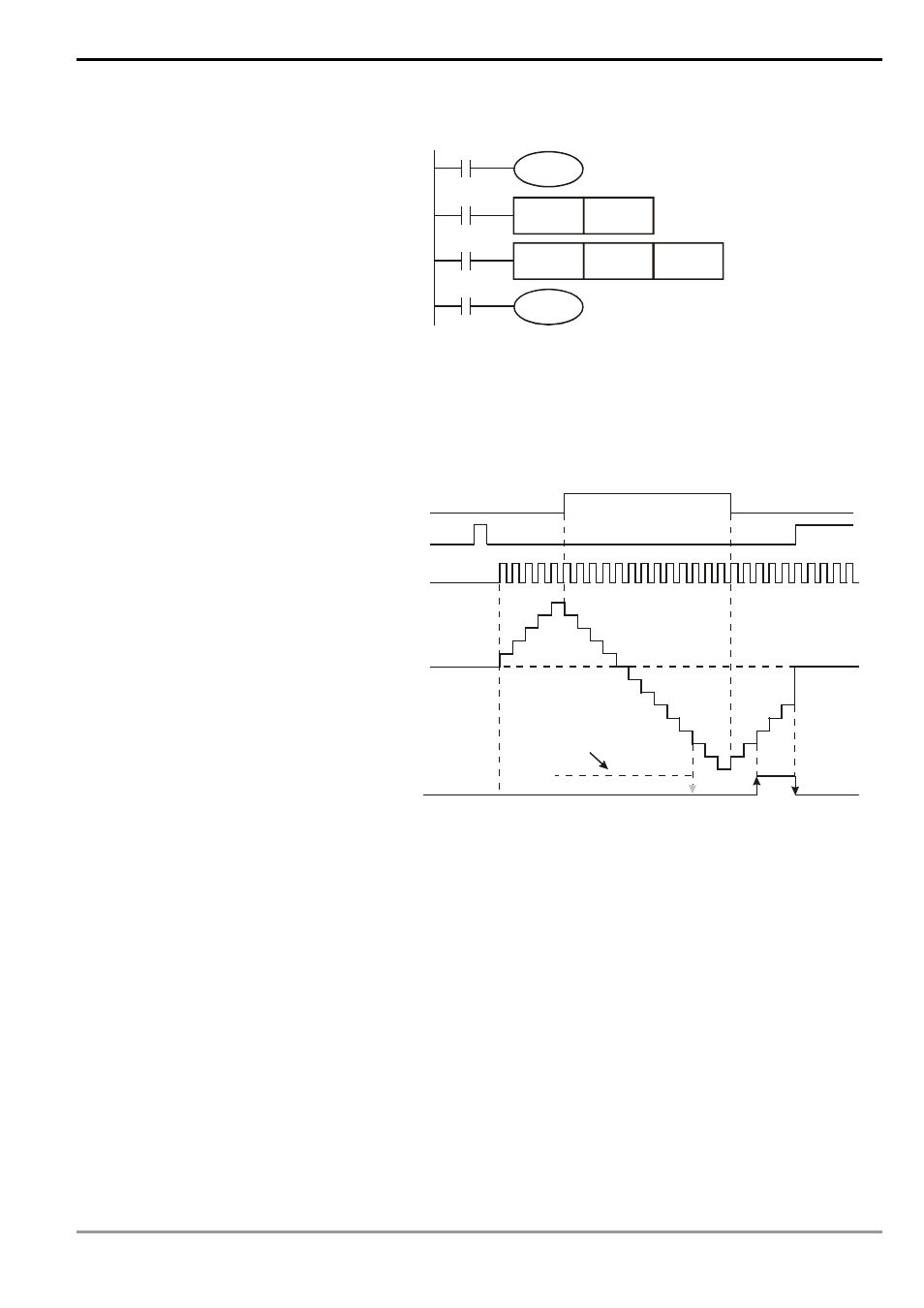
Example:
LD
X10
OUT M1200
LD X11
RST C200
LD X12
CNT
C200 K-5
LD C200
OUT Y0
C200
Y0
X12
C200
K-5
DCNT
X11
C200
RST
X10
M1200
a) X10 drives M1200 to determine
whether C200 is an addition or
subtraction counter.
b) When X11 goes from Off to On, RST
instsruction will be executed and the
PV in C200 will be cleared to “0” and
the contact will be Off.
c) When X12 goes from Off to On, the PV
in the counter will count up (plus 1) or
count down (minus 1).
d) When the PV in C200 changes from
K-6 to K-5, the contact of C200 will go
from Off to On. When the PV in C200
changes from K-5 to K-6, the contact of
C200 will go from On to Off.
e) If you use MOV instruction, WPLSoft
or HPP to send a value bigger than the
SV to the present value register of C0,
next time when X1 goes from Off to
On, the contact of counter C0 will be
On and its PV will equal SV.
X10
X11
X12
0
1
2
3
4
5
4
3
2
1
0
-1
-2
-3
-4
-5
-6
-7
-8
0
-7
-6
-5
-4
-3
Contacts
Y0, C0
Accumulatively
increasing
Accumulatively
increasing
Progressively
decreasing
PV in
C200
When the output contact
was On.
32-bit high-speed addition/subtraction counters C235 ~ C255:
1. The setup range of 32-bit counter: K-2,147,483,648 ~ K2,147,483,647
2. Addition or subtraction of C235 ~ C244 is designated by On/Off status of special auxiliary relays M1235 ~ M1244.
For example, when M1235 = Off, C235 will be an addition counter; when M1235 = On, C235 will be a subtraction
counter.
3. Addition or subtraction of C246 ~ C255 is designated by On/Off status of special auxiliary relays M1246 ~ M1255.
For example, when M1246 = Off, C246 will be an addition counter; when M1246 = On, C246 will be a subtraction
counter.
4. The SV can be constant K or data register D (excluding special data registers D1000 ~ D1999). Data register D