Delta Electronics Programmable Logic Controller DVP-PLC User Manual
Page 371
7 Application Instructions API 50-99
D V P - P L C A P P L I C AT I O N M A N U A L
7-87
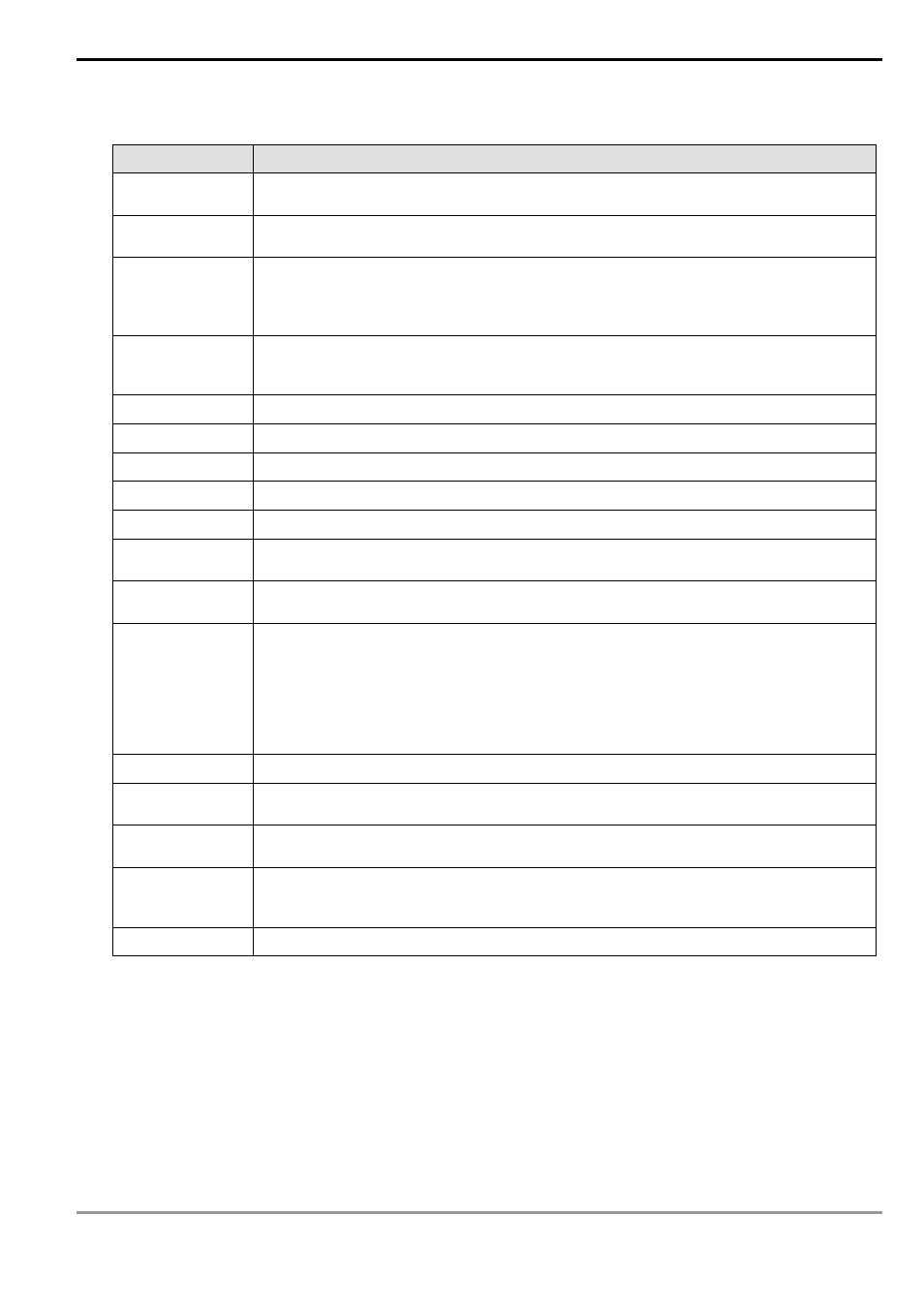
2. Special data register for the RS-485 communication of RS/MODRD/MODWR/FWD/REV/STOP/RDST/RSTEF
/MODRW instructions
Special D
Function
D1038
For setting up the data responding delay time when a PLC MPU using RS-485
communication is used as a slave. Range: 0 ~ 10,000 (unit: 0.1ms)
D1050 ~ D1055
When MODRD/RDST instruction is executed, PLC will automatically convert the ASCII
characters in D1070 ~ D1085 into hex and store the hex value in D1050 ~ D1055.
D1070 ~ D1085
When the RS-485 communication instructions built in PLC are executed, the receiving
end will respond with a message and the messages will be stored in D1070 ~ D1085.
You can check on the responded data stored in these registers (not applicable for RS
instruction).
D1089 ~ D1099
When the RS-485 communication instructions built in PLC are executed, the data sent
will be stored in D1089 ~ D1099. You can check on whether the data sent are correct by
checking these registers (not applicable for RS instruction).
D1120
RS-485 communication protocol. See the next table for more details.
D1121
The communication address of PLC when it operates as a slave.
D1122
Remaining number of words of the data being sent
D1123
Remaining number of words of the data being received
D1124
Definition of the start word (STX). See the table above for more details.
D1125
Definition of the first end word (ETX1) of RS instruction. See the table above for more
details.
D1126
Definition of the second end word (ETX2) of RS instruction. See the table above for more
details.
D1129
Abnormal communication time-out (in ms). When D1129 = 0, there will be no time-out
occurring. When D1129 > 0 and RS/MODRD/
MODWR/FWD/REV/STOP/RDST/RSTEF/MODRW instructions are being executed, if
the first word has not been received within designated time or the time interval between
any two words exceeds the value (>0) after PLC enters the receiving mode, PLC will
automatically set M1129 to On. You can also use M1129 for handling the communication
time-out. Please be noted that you have to reset M1129 after the time-out.
D1130
Error code sent back by Modbus
D1168
For RS instruction, when the received number of words = the low byte of D1168, the
interruption I150 will be triggered.
D1169
For RS instruction, when the received data length = the low byte of D1169, the
interruption I160 will be triggered. When D1169 = 0, I160 will not be triggered.
D1256 ~ D1295
When the RS-485 communication instruction MODRW built in PLC is executed, the data
sent will be stored in D1256 ~ D1295. You can check on whether the data sent are
correct by checking these registers.
D1296 ~ D1311
For MODRW instruction, PLC will automatically convert the ASCII characters into hex.