Delta Electronics Programmable Logic Controller DVP-PLC User Manual
Page 568
9 Application Instructions API 150-199
DVP-PLC Application Manual
9-96
7. D1340, D1352, D1379 and D1380 are the settings of start/end frequencies of CH0 ~ CH3. The minimun
frequency is 10Hz and default is 200Hz.
8. D1343, D1353, D1381 and D1382 are the settings of the time of the first segment and the last deceleration
segment of CH0 ~ CH3. The acceleration/deceleration time cannot be shorter than 10ms. The outptu will be
operated in 10ms if the time set is shorter than 10ms or longer than 10,000ms. The dafault setting is 100ms.
9. D1198, D1199, D1478 and D1479 are the output/input ratio of the close loop control in CH0 ~ CH3. K1 refers to
1 output pulse out of the 100 target feedback input pulses; K200 refers to 200 output pulses out of the 100
target feedback input pulses. D1198, D1199, D1478 and D1479 are the numerators of the ratio (range: K1 ~
K10,000) and the denominator is fixed as K100 (the user does not have to enter a denominator).
10. M1305, M1306, M1532 and M1533 are the direction signal flags for CH0 ~ CH3. When S
2
is a positive value,
the output will be in forward direction and the flag will be Off. When S
2
is a negative value, the output will be in
backward direction and the flag will be On.
Close Loop Explanations:
1. Function: Immediately stop the high-speed pulse output according to the number of feedback pulses or external
interruption signals.
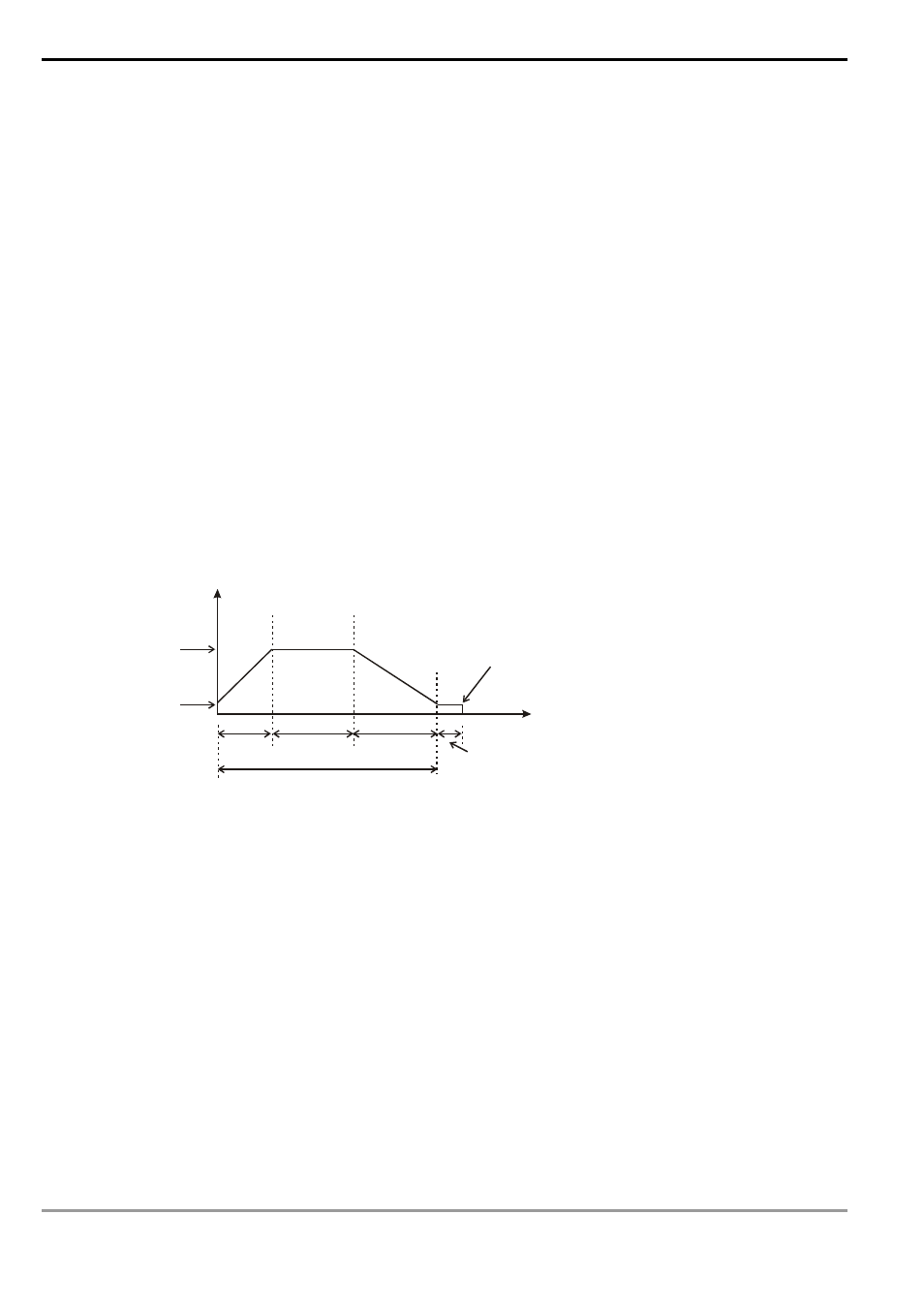
2. The
execution:
Frequency
Time
Number
C high speed counting = target number of feedbacks
or
occurrence of external interruption
Target frequency
Start/end frequency
Acceleration
tim e
High speed time
Deceleration time
Idling time
Number of output pulses =
target number of feedbacks x percentage value/100
3. How to adjust the time for the completion of the positioning:
a) The time for the completion of the positioning refers to the time for “acceleration + high speed +
deceleration + idling” (see the figure above). For example, you can increase or decrease the entire number
of output pulses by making adjustment on the percentage value and further increase or decrease the time
required for the positioning.
b) Among the four segments of time, only the idling time cannot be adjusted directly by the user. However, you
can determine if the execution result is good or bad by the length of the idling time. In theory, a bit of idling
left is the best result for a positioning.
c) Owing to the close loop operation, the length of idling time will not be the same in every execution.
Therefore, when the content in the special D for displaying the actial number of output pulses is smaller or
larger than the calculated number of output pulses (taget number of feedbacks x percentage value/100),
you can improve the situation by adjusting the percentage value, acceleration/decelartion time or target
frequency.