4 step ladder instructions – Delta Electronics Programmable Logic Controller DVP-PLC User Manual
Page 176
4 Step Ladder Instructions
DVP-PLC Application Manual
4-6
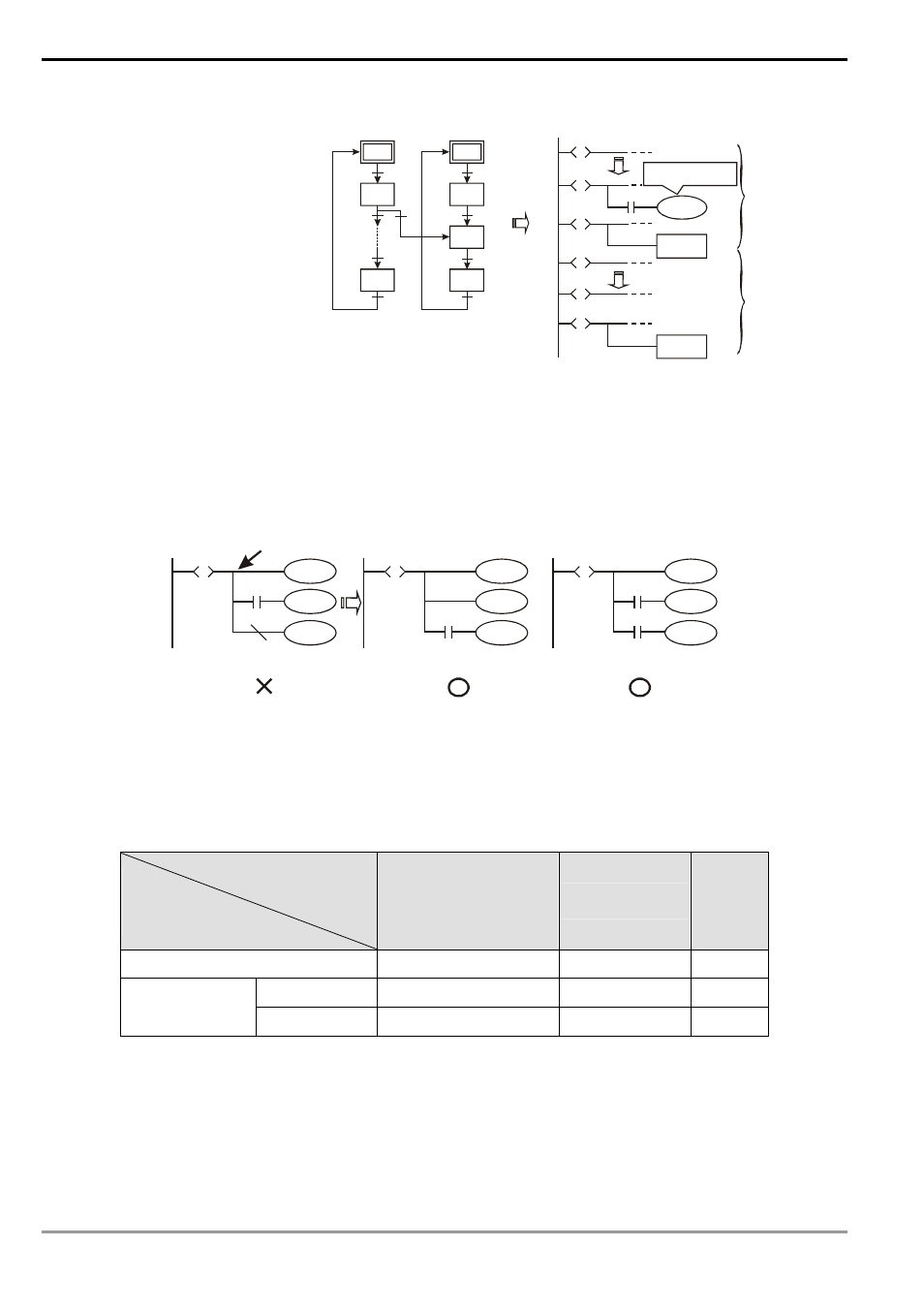
e Separating steps
in different
sequences.
SFC: Ladder diagram:
S0
S21
S23
X2
OUT
OUT
S1
S41
S43
OUT
S42
S42
S21
S
S0
S
S1
S
X2
S42
S
S43
S
RET
S23
S
RET
Step sequence
initiated by S0
Step sequence
initiated by S1
Using OUT S42
Two different step sequence: S0 and S1
S23 returns to initial step S0 by using OUT.
S43 returns to initial step S1 by using OUT.
Driving the separating
of steps
6. Cautions for Driving Output Point:
See the figure below. After the step point and once LD or LDI instructions are written into the second line, the
bus will not be able to connect directly to the output coil, and errors will occur in the compilation of the ladder
diagram. You have to correct the diagram into the diagram in the right hand side for a correct compilation.
Y0
S
S
Y1
Y2
M0
n
Y0
S
S
Y2
Y1
n
M0
Y0
S
S
Y1
Y2
M0
n
M1000
BUS
or
Modifying the
position of M0.
Normally open
contact in RUN
mode
7. Restrictions on Using Some Instructions:
The program of every step is the same as a general ladder diagram, in which you can use all kinds of
series/parallel circuits or instructions. However, there are restrictions on some of the instructions.
Basic instructions applicable in a step
Instruction
Step
LD/LDI/LDP/LDF
AND/ANI/ANDP/ANDF
OR/ORI/ORP/ORF
INV/OUT/SET/RST
ANB/ORB
MPS/MRD/MPP
MC/MCR
Initial step/general step
Yes
Yes
No
General output
Yes
Yes
No
Divergence/
convergence step Step transfer
Yes
No
No
DO NOT use MC/MCR instruction in the step.
DO NOT use STL instruction in a general subroutine or interruption subroutine.
You can still use CJ instruction in STL instruction, but this will make the actions more complicated. We do not
recommend you do so.