Delta Electronics Programmable Logic Controller DVP-PLC User Manual
Page 352
7 Application Instructions API 50-99
D V P - P L C A P P L I C AT I O N M A N U A L
7-68
3. When there is 1 group of 4-digit 7-segment display, n = 0 ~ 3.
a) Connect the already decoded 7-segment display terminals 1, 2, 4, 8 in parallel an connect them to Y10 ~
Y13 on the PLC. Connect the latch terminals of each digit to Y14 ~ Y17 on the PLC.
b) When X10 = On, the instruction will be executed and the content in D10 will be sent to the 7-segment
displays in sequence by the circulation of Y14 ~ Y17.
4. When there is 2 groups of 4-digit 7-segment display, n = 4 ~ 7.
a) Connect the already decoded 7-segment display terminals 1, 2, 4, 8 in parallel an connect them to Y20 ~
Y23 on the PLC. Connect the latch terminals of each digit to Y14 ~ Y17 on the PLC.
b) The contents in D10 are sent to the first group 7-segment display. The contents in D11 are sent the the
second group 7-segment display. If D10 = K1234 and D11 = K4321, the first group will display 1 2 3 4, and
the second group will display 4 3 2 1.
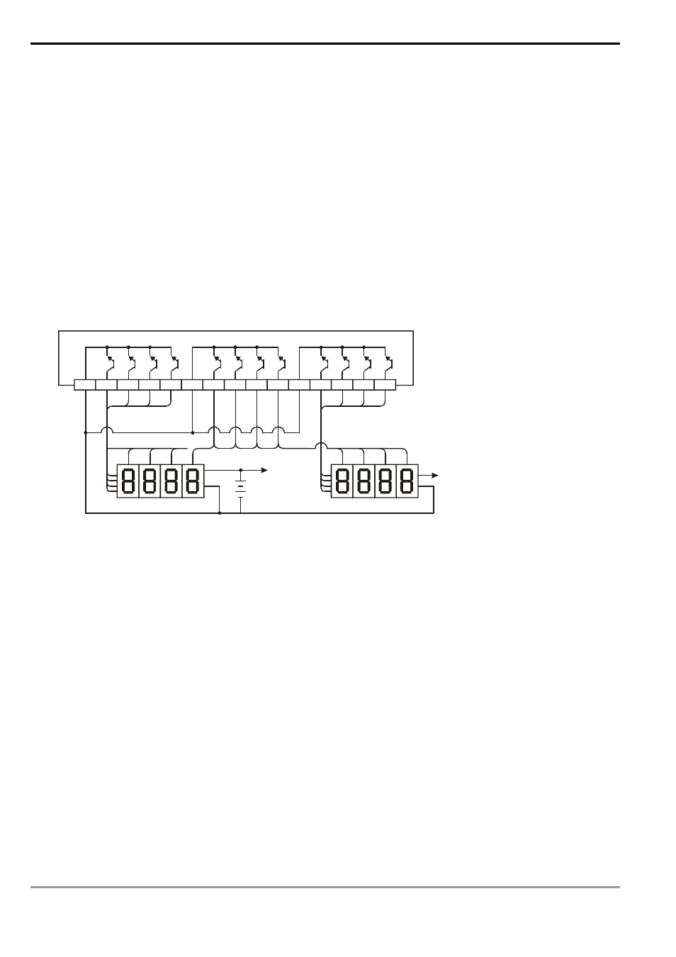
5. Wiring of the 7-segment display scan output:
COM Y10
Y11
Y12
Y13
Y14
Y15
Y16
Y17
Y20
Y21
Y22
Y23
COM
COM
1
2
4
8
10
0
10
1
10
2
10
3
10
3
10
2
10
1
10
0
V+
10
3
10
2
10
1
10
0
V+
1
2
4
8
1
2
4
8
The first group
The second group
Remarks:
1. ES/EX/SS series MPU (V4.9 and above) supports this instruction but only supports 1 group of 4-digit 7-segment
display and 8 points of output. This instruction can only be used once in the program. Range of n: 0 ~ 3.
2. D of ES/EX/SS series MPU can only designate Y0.
3. When this instruction is executed, the scan time has to be longer than 10ms. If the scan time is shorter than
10ms, please fix the scan time at 10ms.
4. n is for setting up the polarity of the transistor output and the number of groups of the 4-digit 7-segment display.
5. The output point must be a transistor module of NPN output type with open collector outputs. The output has to
connect to a pull-up resistor to VCC (less than 30VDC). Therefore, when output point Y is On, the signal output
will be in low voltage.