1 basic principles of plc ladder diagram – Delta Electronics Programmable Logic Controller DVP-PLC User Manual
Page 11
1 Basic Principles of PLC Ladder Diagram
DVP-PLC Application Manual
1-7
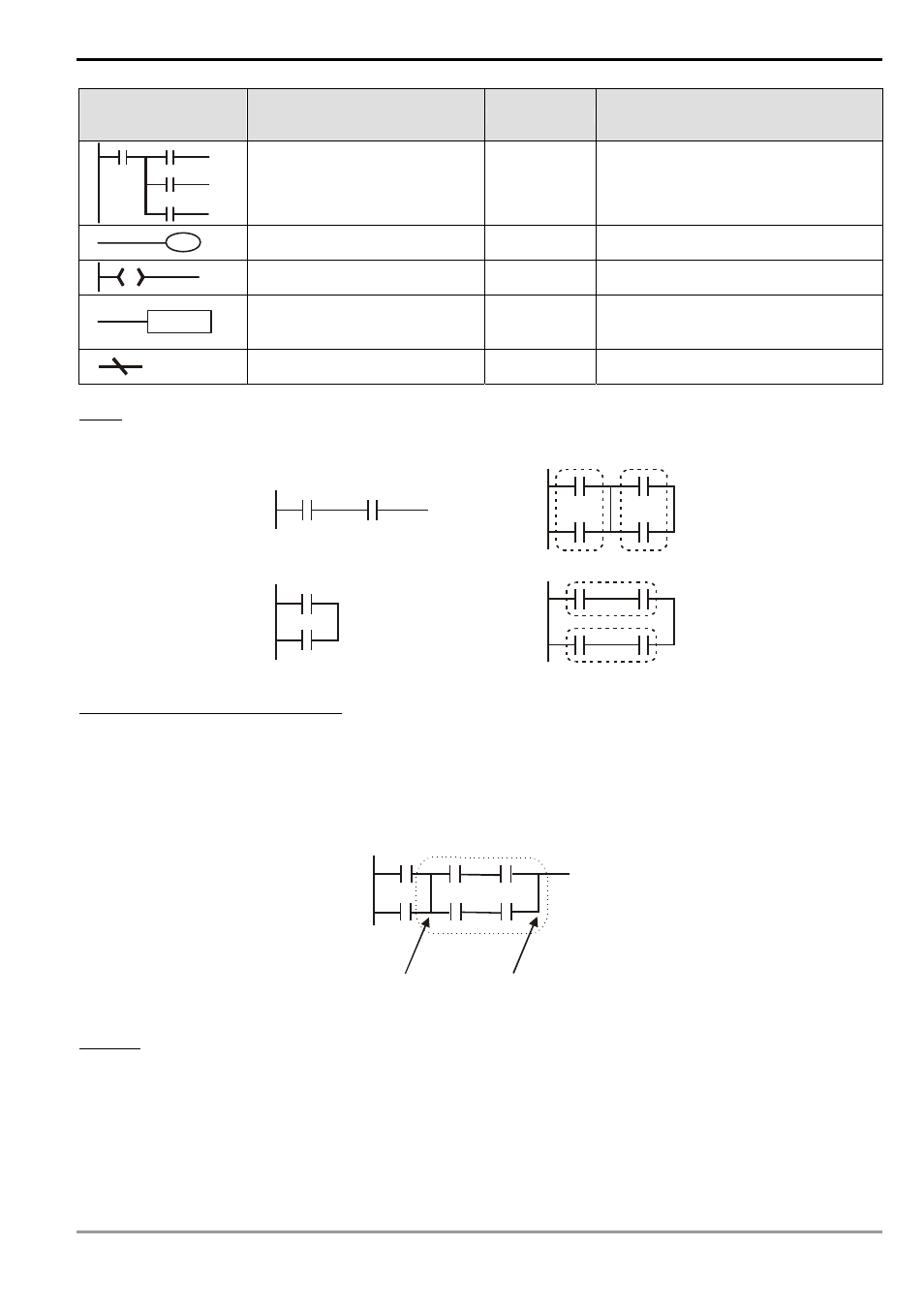
Structure
Explanation
Instruction
Devices Used
Multiple output
MPS
MRD
MPP
-
Coil driven output instruction
OUT
Y, M, S
S
S
Step ladder
STL
S
Basic instruction
Application instruction
Application
instructions
See Ch.3 for basic instructions
(RST/SET and CNT/TMR) and Ch.5 ~
10 for application instructions
Inverse logic
INV
-
Block:
A block is a series or parallel operation composed of more than 2 devices. There are series block and parallel block.
Series block
Parallel block
Separation line and combination line:
The vertical line is used for separating the devices. For the devices on the left, the vertical line is a combination line,
indicating that there are at least 2 rows of circuits on the left connected with the vertical line. For the devices on the
right, the vertical line is a separation line, indicating that there are at least 2 rows of circuits interconnected on the right
side of the vertical line).
1
2
Combination line for block 1
Separation line for block 2
Combination line for block 2
Network:
A complete block network is composed of devices and all kinds of blocks. The blocks or devices connectable by a
vertical line or continuous line belong to the same network.