2 functions of devices in dvp-plc, 1 all devices in dvp-plc – Delta Electronics Programmable Logic Controller DVP-PLC User Manual
Page 29
2 Functions of Devices in DVP-PLC
DVP-PLC Application Manual
2-1
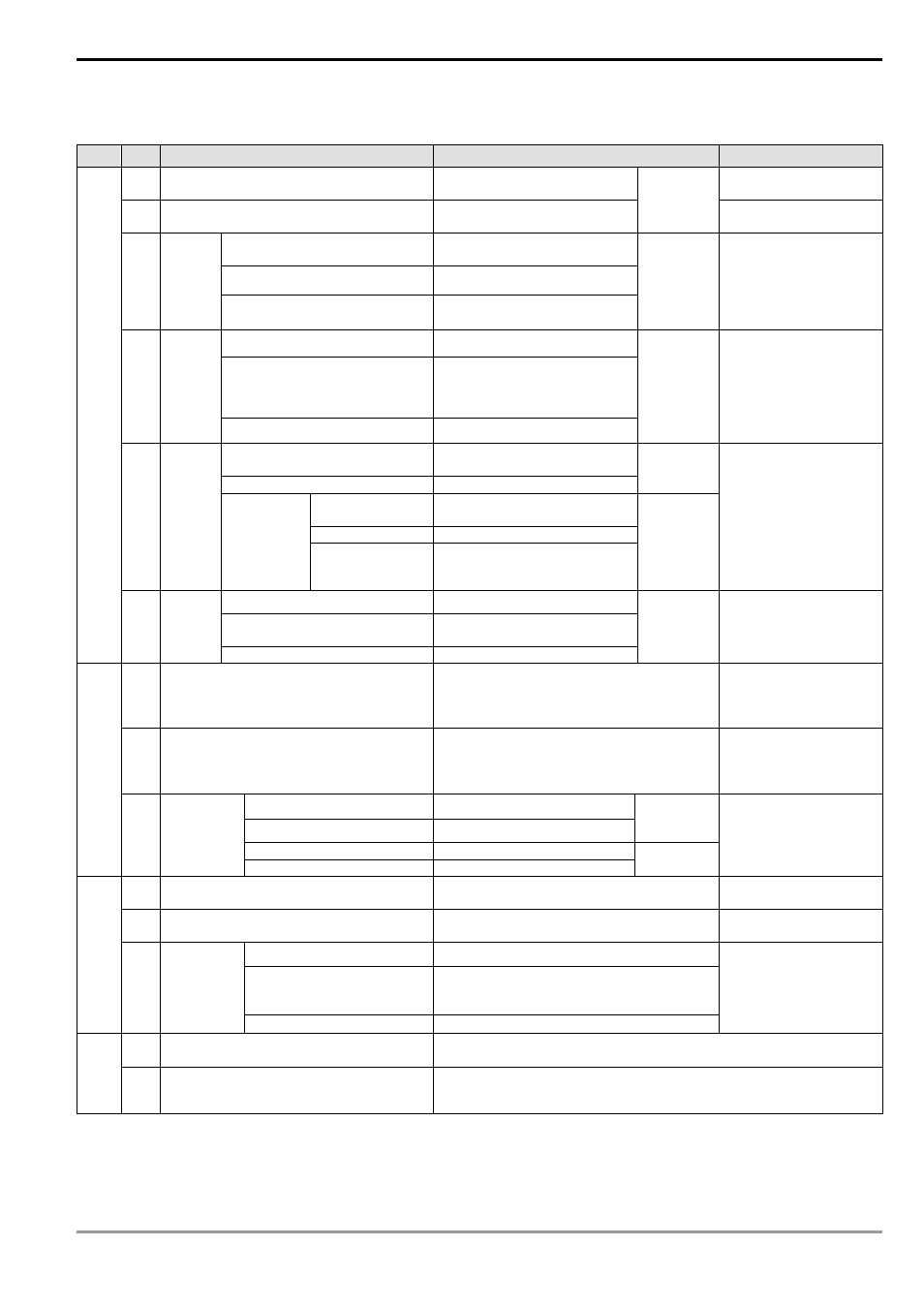
2.1 All Devices in DVP-PLC
ES/EX/SS series MPU:
Type
Device
Item
Range
Function
X
External input relay
X0 ~ X177, 128 points, octal
Corresponds to external
input points
Y
External output relay
Y0 ~ Y177, 128 points, octal
Total
256 points Corresponds to external
output points
General purpose
M0 ~ M511, M768 ~ M999, 744
points
Latched*
M512 ~ M767, 256 points
M
Auxiliary
relay
Special purpose
M1000 ~ M1279, 280 points
(some are latched)
Total
1,280 points
The contact can be
On/Off in the program.
100ms timer
T0 ~ T63, 64 points
10ms timer (M1028 = On)
T64 ~ T126, 63 points (M1028
= Off: 100ms)
T Timer
1ms timer
T127, 1 points
Total
128 points
Timer indicated by TMR
instruction. If timing
reaches its target, the T
contact of the same No.
will be On.
16-bit counting up
(general purpose)
C0 ~ C111, 112 points
16-bit counting up (latched*)
C112 ~ C127, 16 points
Total
128 points
1-phase 1 input
C235 ~ C238, C241, C242,
C244, 7 points
1-phase 2 inputs
C246, C247, C249, 3 points
C Counter
32-bit
counting
up/down
high-speed
counter
(latched*)
2-phase 2 inputs
C251, C252, C254, 3 points
Total
13 points
Counter indicated by
CNT (DCNT) instruction.
If counting reaches its
target, the C contact of
the same No. will be On.
Initial step (latched*)
S0 ~ S9, 10 points
Zero return (latched*)
S10 ~ S19, 10 points (used with
IST instruction)
Relay (
bit)
S Step
Latched*
S20 ~ S127, 108 points
Total
128 points
Used for SFC.
T
Present value of timer
T0 ~ T127, 128 points
When the timing
reaches the target, the
contact of the timer will
be On.
C
Present value of counter
C0 ~ C127, 16-bit counter, 128 points
C235 ~ C254, 32-bit counter, 13 points
When the counting
reaches the target, the
contact of the counter
will be On.
General purpose
D0 ~ D407, 408 points
Latched*
D408 ~ D599, 192 points
Total
600 points
Special purpose
D1000 ~ D1311, 312 points
Regist
er (word
dat
a)
D
Data
register
Index indication
E, F, 2 points
Total
312 points
Memory area for data
storage; E, F can be
used for index
indication.
N
For master control nested loop
N0 ~ N7, 8 points
Control point for main
control loop
P
For CJ, CALL instructions
P0 ~ P63, 64 points
Position index for CJ
and CALL
External interruption
I001, I101, I201, I301, 4 points
Timed interruption
I6□□, 1 point (□□=10 ~ 99, time base =
1ms ) (for V5.7 and above)
Pointer
I Interruption
Communication interruption
I150, 1 point
Position index for
interruption subroutine.
K Decimal
form
K-32,768 ~ K32,767 (16-bit operation)
K-2,147,483,648 ~ K2,147,483,647 (32-bit operation)
Const
a
nt
H Hexadecimal
form
H0000 ~ HFFFF (16-bit operation)
H00000000 ~ HFFFFFFFF (32-bit operation)
* The latched area is fixed and cannot be changed.