Delta Electronics Programmable Logic Controller DVP-PLC User Manual
Page 399
7 Application Instructions API 50-99
D V P - P L C A P P L I C AT I O N M A N U A L
7 - 115
The example program of the instruction delay:
M1002
MOV
K10
D3
M0
TMR
T0
D3
T0
RST
T0
MOV
K50
D2
D1
D0
>
MOV
K-50
D2
D1
D0
<
MOV
K0
D2
D1
D0
=
ADD
D2
D1
D1
M10
CMP
D2
K0
M10
D0
D1
<
MOV
D0
D1
M12
D0
D1
>
MOV
D0
D1
M0
PID
D1
D1116
D10
D5
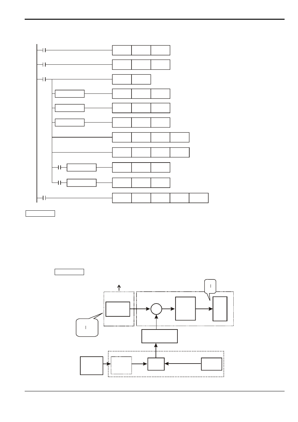
Application 2 Speed control system and pressure control system work individually (use diagram of Example 2).
Purpose: After the speed control operates in open loop for a period of time, adding into it the pressure control system
(PID instruction) for close loop control.
Explanation: Since the speed and pressure control systems are not interrelated, we have to structure a open loop for
speed control first following by a close loop pressure control. If you fear that the control instruction of the
pressure control system changes too fast, you can consider to add the instruction delay illustrated in
Application 1 into the control. See the control diagram below.
D40
0
255
0rpm
3,000rpm
D30
D32
D1116
D31
+
+
M3
PID
PV
MV
D5
D1
SV
D0
D1110
Speed
instruction
M2 = On
Speed
converted
to
voltage
AC
motor
drive
MV converted to
accel/decel value
M0 = On
Pressure
instruction
Delay
(optional)
M1 = On
Pressure
meter