2 functions of devices in dvp-plc – Delta Electronics Programmable Logic Controller DVP-PLC User Manual
Page 134
2 Functions of Devices in DVP-PLC
DVP-PLC Application Manual
2-106
a) Using Y10 pulse output
Mode 1 – Planned deceleration
Applicable to: DDRVI and DDRVA instructions
Criteria for executing planned deceleration: Shut down the criteria contact for pulse output instruction and
turn “Off” M1334.
The time from executing planned deceleration to the end of pulse output: The time set in D1343 (for
acceleration/deceleration)
The solid lines in the figure below are the originally planned routes and the dotted lines refer to the routes
after planned deceleration is executed.
Frequency
Target frequency
Start frequency
D1340
Instruction shut down and M1334 = Off
Time
Acceleration/deceleration time
D1343
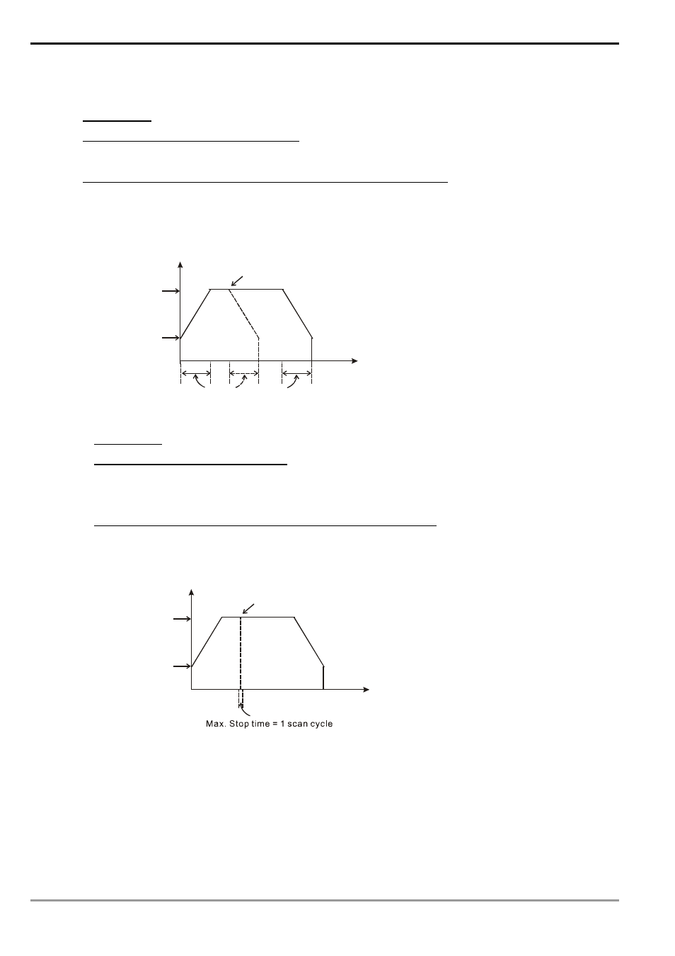
Mode 2 – Output shutdown
Applicable to: DDRVI, DDRVA, PLSY instructions
Criteria for executing output shutdown: Shut down the criteria contact for pulse output instruction and turn
“On” M1334.(Because PLSY does not have acceleration/deceleration setting, M1334 does not need to
be set in PLSY)
The time from executing output shutdown to the end of pulse output: Max. 1 scan cycle.
The solid lines in the figure below are the originally planned routes and the dotted lines refer to the routes
after output shutdown is executed.
Frequency
Target frequency
Start frequency
D1340
Instruction shut down and M1334 = On
Time
Mode 3 – Immediate output shutdown
Applicable to: DDRVI, DDRVA, PLSY instructions
Criteria for executing immediate output shutdown: M1310 = On (set before executing the instruction) and
the criteria triggers set in X10 (D1166 = K0 refers to rising-edge; D1166 = K1 refers to falling-edge)
The time from executing immediate output shutdown to the end of pulse output: Max. 1 pulse time.
The solid lines in the figure below are the originally planned routes and the dotted lines refer to the
routes after X10 is triggered.