Delta Electronics Programmable Logic Controller DVP-PLC User Manual
Page 586
10 Application Instructions API 200-249
DVP-PLC Application Manual
10-12
API Mnemonic
Operands
Function
240~
246
D OR
※
OR Compare
Controllers
ES/EX/SS SA/SX/SC EH/SV
Bit Devices
Word Devices
Program Steps
Type
OP
X Y M S K H
KnX
KnY KnM KnS T
C
D
E
F
S
1
*
* *
*
*
*
*
*
*
*
*
S
2
*
*
*
*
*
*
*
*
*
*
*
OR*: 5 steps
DOR*: 9 steps
PULSE 16-bit 32-bit
ES EX SS SA SX SC EH SV ES EX SS SA SX SC EH SV ES EX SS SA SX SC EH SV
Operands:
S
1
: Data source device 1 S
2
: Data source device 2
Explanations:
1. See the specifications of each model for the range of operands.
2. This instruction compares the content in S
1
and S
2
. Take API240 (OR=) for example, if the result is “=”, the
continuity of the instruction is enabled. If the result is “≠”, the continuity of the instruction is disabled.
3. OR
※
(
※:
=, >, <, <>, ≤, ≥
)
is an comparison instruction used on parallel contacts.
API No.
16 -bit
instruction
32 -bit
instruction
Continuity
condition
No-continuity
condition
240
OR=
D
OR=
S
1
=S
2
S
1
≠S
2
241
OR>
D
OR>
S
1
>S
2
S
1
≦S
2
242
OR<
D
OR<
S
1
<S
2
S
1
≧S
2
244
OR<>
D
OR<>
S
1
≠S
2
S
1
=S
2
245
OR<=
D
OR<=
S
1
≦S
2
S
1
>S
2
246
OR>=
D
OR>=
S
1
≧S
2
S
1
<S
2
4. When 32-bit counters (C200 ~ C255) are used in this instruction for comparison, make sure to adopt 32-bit
instruction (DOR
※
). If 16-bit instructions (OR
※
) is adopted, a “program error” will occur and the ERROR
indicator on the MPU panel will flash.
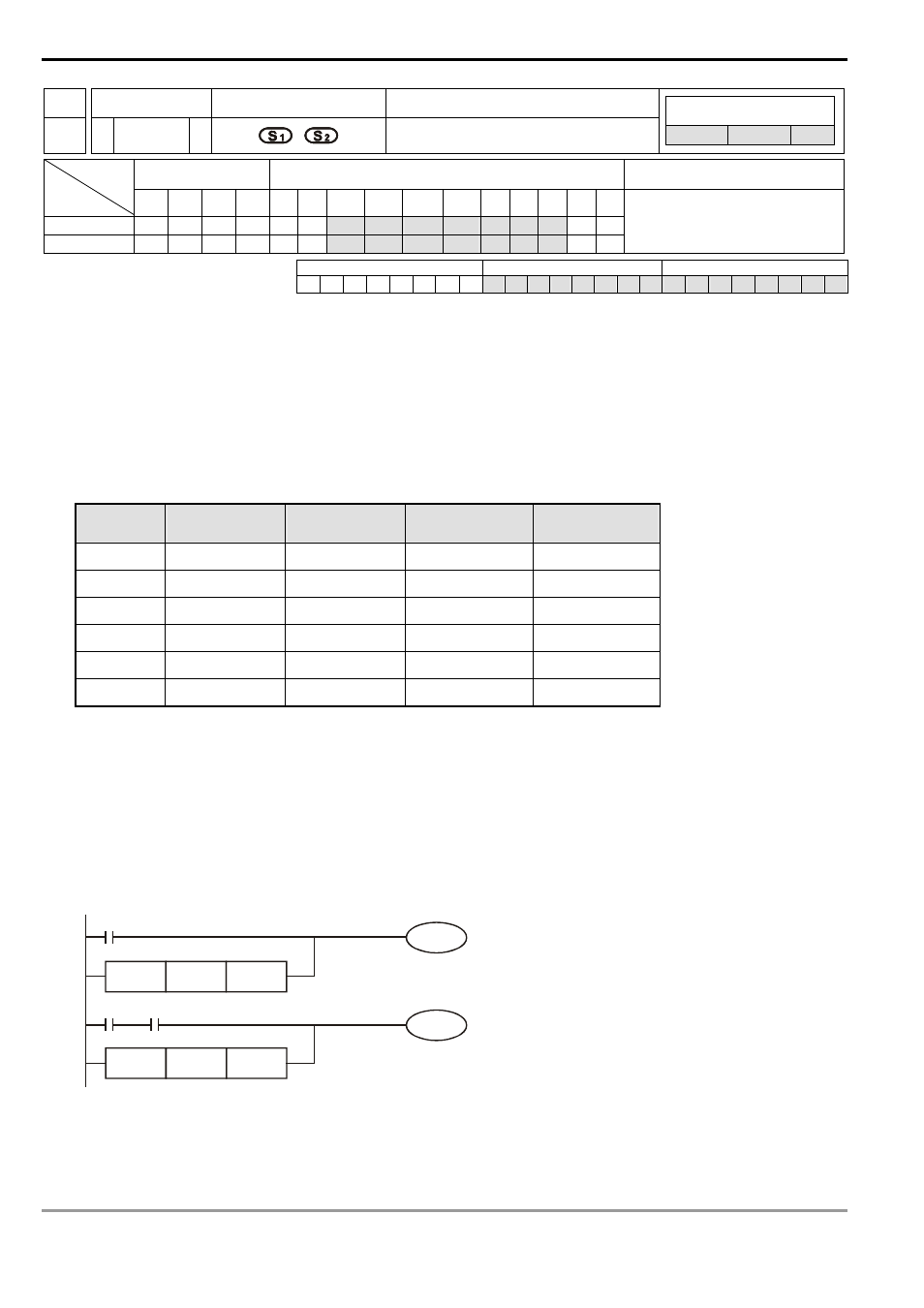
Program Example:
1. When X1 = On and the present value of C10 = K200, Y0 = On.
2. M60 will be On when X2 = On, M30 = On and the content in 32-bit register D100 (D101) ≥ K100,000.
OR=
K200
C10
DOR>
D100 K100000
Y0
X2
X1
M30
M60
=