Delta Electronics Programmable Logic Controller DVP-PLC User Manual
Page 410
8 Application Instructions API 100-149
DVP-PLC Application Manual
8-8
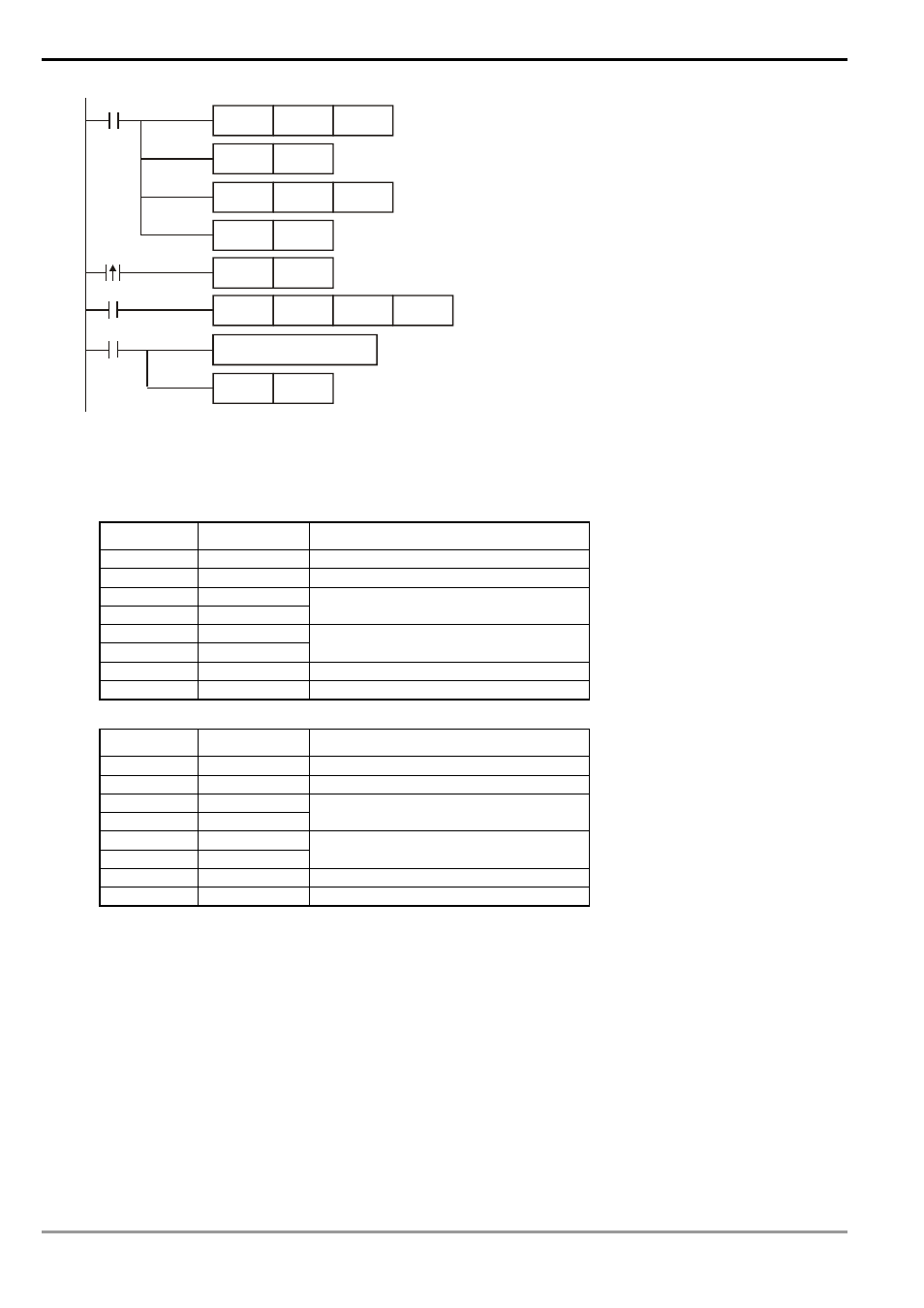
MOV
D1120
H87
M1002
SET
M1120
MOV
D1129
K100
M1127
RST
M1127
receiving
completed
Set up communication protocol 9600, 8, E, 1
Retain communication protocol
Set up communication time-out: 100ms
Process of receiving data
Sending/receiving of data is completed.
The flag is reset.
SET
M1122
Set up as sending flag
X0
The received data in hex are stored in D1070 ~ D1085.
SET
M1143
Set up as RTU mode
X0
MODWR
K1
H2000
Set up communication instruction device address 01
data address H2000 Write in data H12
H12
PLC VFD-S, PLC sends: 01 06 2000 0012 02 07
VFD-S PLC, PLC receives: 01 06 2000 0012 02 07
Registers for sent data (sending messages)
Register DATA
Explanation
D1089 low
01 H
Address
D1090 low
06 H
Function
D1091 low
20 H
D1092 low
00 H
Data address
D1093 low
00 H
D1094 low
12 H
Data contents
D1095 low
02 H
CRC CHK Low
D1096 low
07 H
CRC CHK High
Registers for received data (responding messages)
Register DATA
Explanation
D1070 low
01 H
Address
D1071 low
06 H
Function
D1072 low
20 H
D1073 low
00 H
Data address
D1074 low
00 H
D1075 low
12 H
Data contents
D1076 low
02 H
CRC CHK Low
D1077 low
07 H
CRC CHK High
Program Example 3:
1. In the communication between PLC and VFD-S series AC motor drive (ASCII Mode, M1143 = Off), retry when
communication time-out, data receiving error and sending address error occur.
2. When X0 = On, PLC will write H1770(K6000) into VFD-S data adress H0100 of device 01.
3. M1129 will be On when communication time-out occurs. The program will trigger M1129 and send request to
M1122 for writing the data again.
4. M1140 will be On when data receiving error occurs. The program will trigger M1140 and send request to M1122
for writing the data again.
5. M1141 will be On when sending address error occurs. The program will trigger M1141 and send request to
M1122 for writing the data again.