Delta Electronics Programmable Logic Controller DVP-PLC User Manual
Page 320
7 Application Instructions API 50-99
D V P - P L C A P P L I C AT I O N M A N U A L
7-36
7.
D
for all series MPU:
MPU
ES/EX/SS/SA/SX/SC
EH
EH2/SV
Output point
Y0, Y1
Y0, Y2
Y0, Y2, Y4, Y6
8.
EH series MPU has two groups pf A-B phase pulse output CH0 (Y0, Y1) and CH1 (Y2, Y3). EH2/SV series MPU
has four groups pf A-B phase pulse output CH0 (Y0, Y1), CH1 (Y2, Y3), CH2 (Y4, Y5) and CH3 (Y6, Y7). See
remarks of API 57 PLSY for how to set up.
9.
PLSR instruction is a pulse output instruction with acclerating and decelerating functions. The pulses accelerate
from the static status to target speed and decelerates when the target distance is nearly reached. The pulse
output will stop when the target distance is reached.
10. When PLSR instruction is executed, after S
1
, S
2
and S
3
are set, the pulses will output from D. The output starts
at the frequency of increasing S
1
/10 at a time. The time forf every frequency is fixed at S
3
/9.
11. S
1
, S
2
and S
3
can be changed when PLSR instruction is being executed.
12. For ES/EX/SS/SA/SX/SC series MPU, when all the Y0 pulses have been sent, M1029 will be On; when all the
Y1 pulses have been sent, M1030 will be On. Next time when PLSR instruction is enabled, M1029 or M1030 will
be 0 again and after the pulse output is completed, it will become 1 again.
13. For EH/EH2/SV series MPU, when all the CH0 (Y0, Y1) pulses have been sent, M1029 will be On; when all the
CH1 (Y2, Y3) pulses have been sent, M1030 will be On; when CH2 (Y4, Y5) pulses have been sent, M1036 will
be On; when CH3 (Y6, Y7) pulses have been sent, M1037 will be On. Next time when PLSR instruction is
enabled, M1029, M1030, M1036 or M1037 will be 0 again and after the pulse output is completed, they will
become 1 again.
14. During every acceleration section, the number of pulses ( frequency × time) may not all be integers. PLC will
round up the number to an integer before the output. Therefore, the acceleration time of every section may not
be exactly the same. The offset is determined upon the frequency and the decimal after rounding up. In order to
ensure the correct number of output pulses, PLC will supplement insufficient pulses in the last section.
15. For SA/EH series MPU, there is no limitation on the times of using this instruction in the program. However, for
SA/SX/SC/EH series MPU, two instructions can be exeucted at the same time; for EH2/SV series MPU, four
instructions can be executed at the same time.
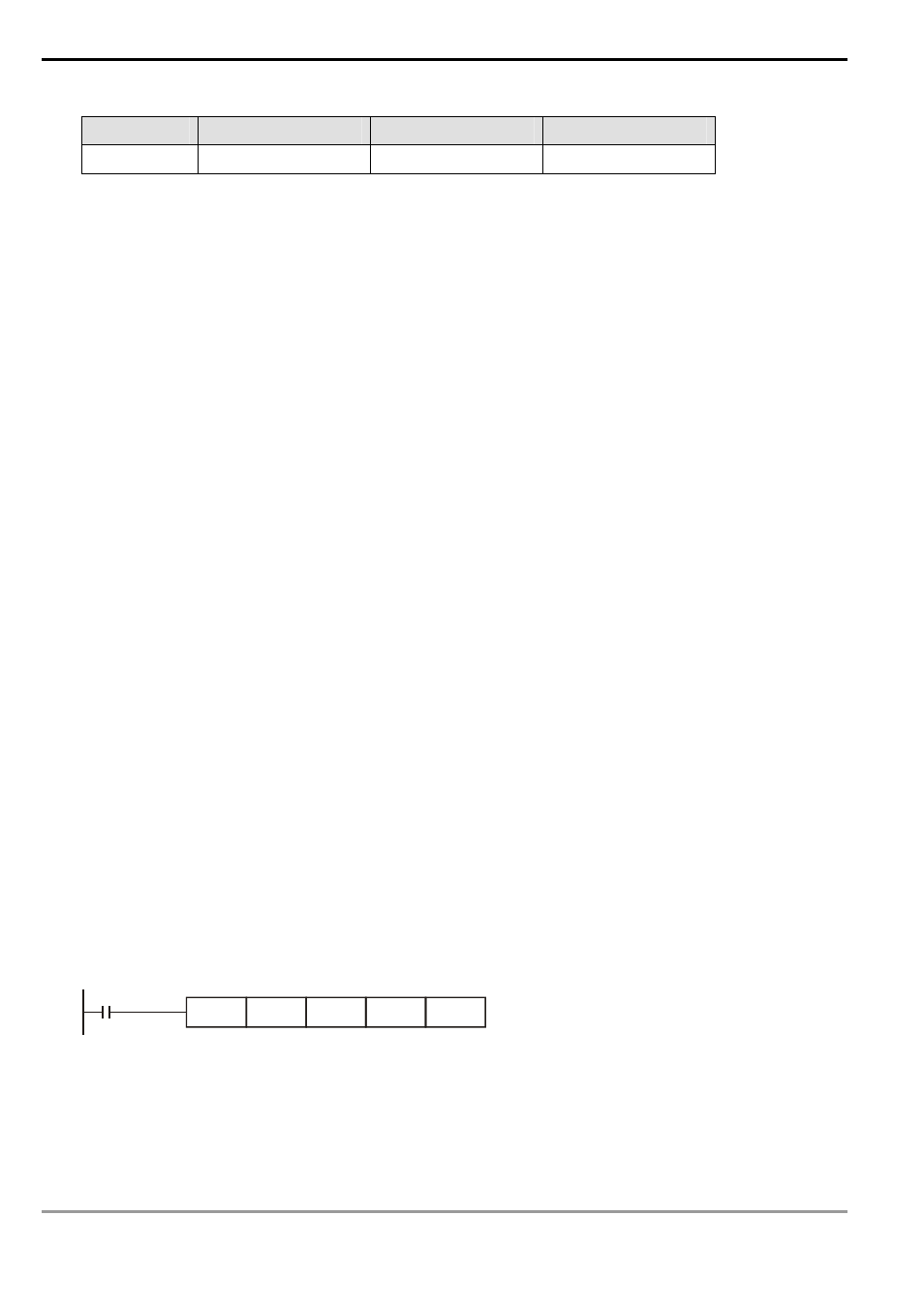
Program Example:
1.
When X0 = On, the pulses will output at the maximum frequency 1,000Hz with the total number D10 at 3,000ms
from Y0. The frequency will increase by 1,000/10Hz at a time and every frequency will last for 3,000/9ms.
2.
When X10 is Off, the output will be interrupted. When X0 is On again, the counting of pulses will start from 0.
X0
PLSR
K1000
D10
K3000
Y0