Delta Electronics Programmable Logic Controller DVP-PLC User Manual
Page 563
9 Application Instructions API 150-199
DVP-PLC Application Manual
9-91
API Mnemonic
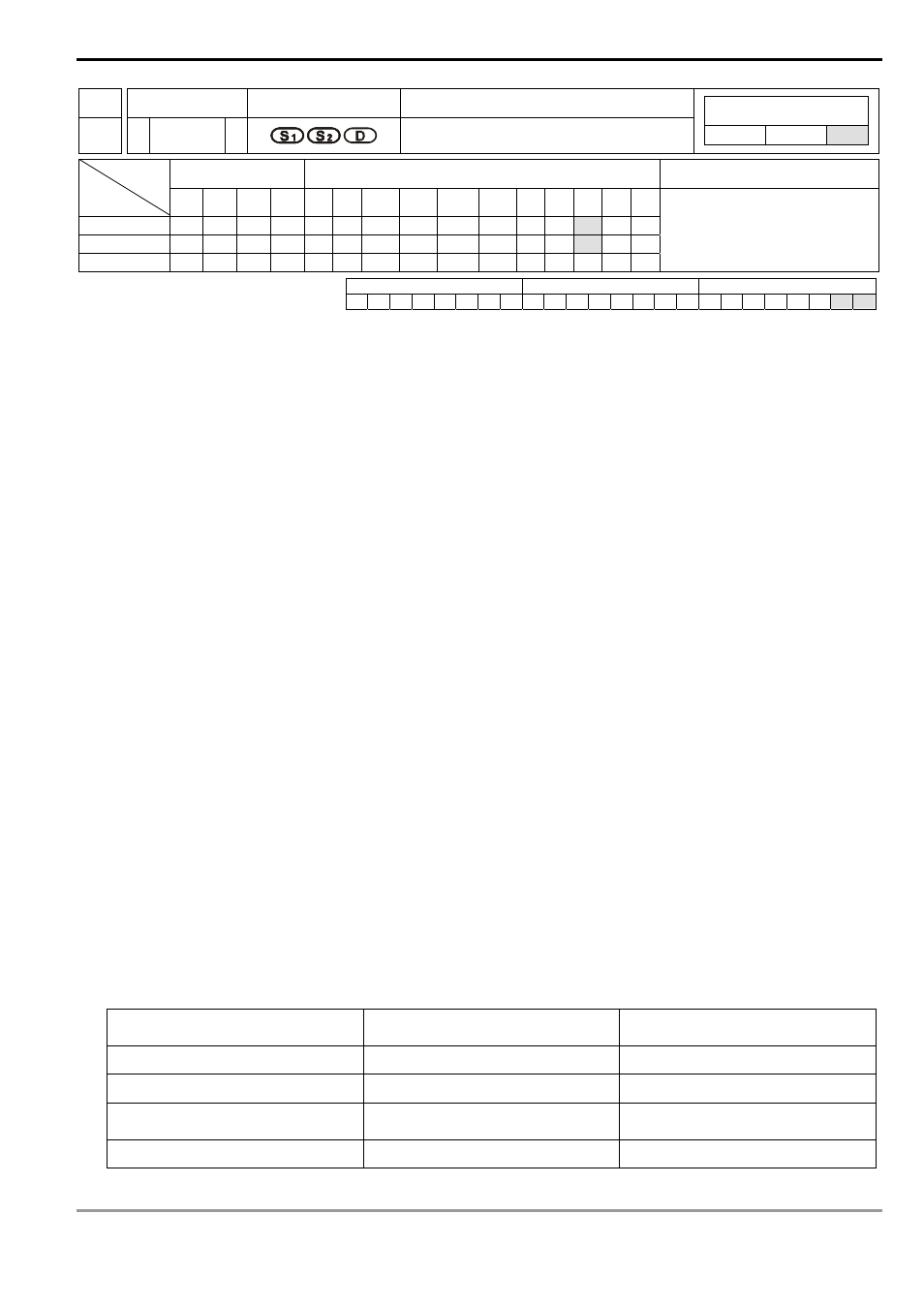
Operands
Function
195
D PTPO
Single-Axis Pulse Output by Table
Controllers
ES/EX/SS SA/SX/SC EH/SV
Bit Devices
Word Devices
Program Steps
Type
OP
X Y M S K H
KnX KnY KnM KnS T
C
D
E
F
S
1
*
S
2
*
D
*
DPTPO: 13 steps
PULSE 16-bit 32-bit
ES EX SS SA SX SC EH SV ES EX SS SA SX SC EH SV ES EX SS SA SX SC EH SV
Operands:
S
1
: Source start device S
2
: Number of segments D: Pulse output device
Explanations:
1. Flags: M1029, M1030, M1334, M1335. See remarks for more details.
2. This instruction only supports EH2/SV series MPU, not EH series.
3. According to the value of S
2
+ 0, every segment consecutively occupy four register D. (S
1
+ 0) refers to output
frequency. (S
1
+ 2) refers to the number of output pulses.
4. When the output frequency of S
1
is less than 1, PLC will automatically modify it as 1. When the value is larger
than 200,000KHz, PLC will automatically modify it as 200,000KHz.
5. S
2
+ 0: number of segments (range: 1 ~ 60). S
2
+ 1: number of segments being executed. Whenever the program
scans to this instruction, the instruction will automatically update the segment No. that is currently being
executed.
6. D can only designate output devices Y0, Y2, Y4 and Y6 and can only perform pulse output control. For the pin for
direction control, the user has to compile other programs to control.
7. This instruction does not offer acceleration and deceleration functions. Therefore, when the instruction is disabled,
the output pulses will stop immediately.
8. In every program scan, each channel can only be executed by one instruction. However, there is no limitation on
the number of times using this instruction.
9. When the instruction is being executed, the user is not allowed to update the frequency or number of the
segments. Changes made will not be able to make changes in the actual output.
Program Example:
1. When X0 = On, the output will be operated according to the set frequency and number of pulses in every
segment.
2. Format of the table:
S
2
= D300, number of segments
(D300 = K60)
S
1
= D0, frequency (S
1
+ 0)
S
1
= D0, number of output pulses
(S
1
+ 2)
K1 (1
st
segment)
D1, D0
D3, D2
K2 (2
nd
segment)
D5, D4
D7, D6
:
:
:
:
:
:
K60 (60
th
segment)
D237, D236
D239, D238