Delta Electronics Programmable Logic Controller DVP-PLC User Manual
Page 387
7 Application Instructions API 50-99
D V P - P L C A P P L I C AT I O N M A N U A L
7-103
API Mnemonic Operands
Function
85
VRRD
P
Volume Read
Controllers
ES/EX/SS SA/SX/SC EH/SV
Bit Devices
Word Devices
Program Steps
Type
OP
X Y M S K H
KnX KnY KnM KnS T
C
D
E
F
S
*
*
D
*
*
*
*
*
*
*
*
VRRD, VRRDP: 5 steps
PULSE 16-bit 32-bit
ES EX SS SA SX SC EH SV ES EX SS SA SX SC EH SV ES EX SS SA SX SC EH SV
Operands:
S
: No. of VR D: Device for storing the volume of VR
Explanations:
1. Range
of
S
: 0 ~ 7; without function card: 0 ~ 1.
2. See the specifications of each model for their range of use.
3. Flags: M1178, M1179. See remarks for more details.
4. VRRD instruction is used for reading 2 points (No.0, No.1) of PLC or the VR rotary switch volume change in the 6
points of the function cards (No.2 ~ No.7) and converting the data into values 0 ~ 255 (stored in D).
5. If you are to set up the timer by the VR volume, simply rotate the VR to modify the set time in the timer. If you are
to acquire a value larger than 255, multiply D by a constant.
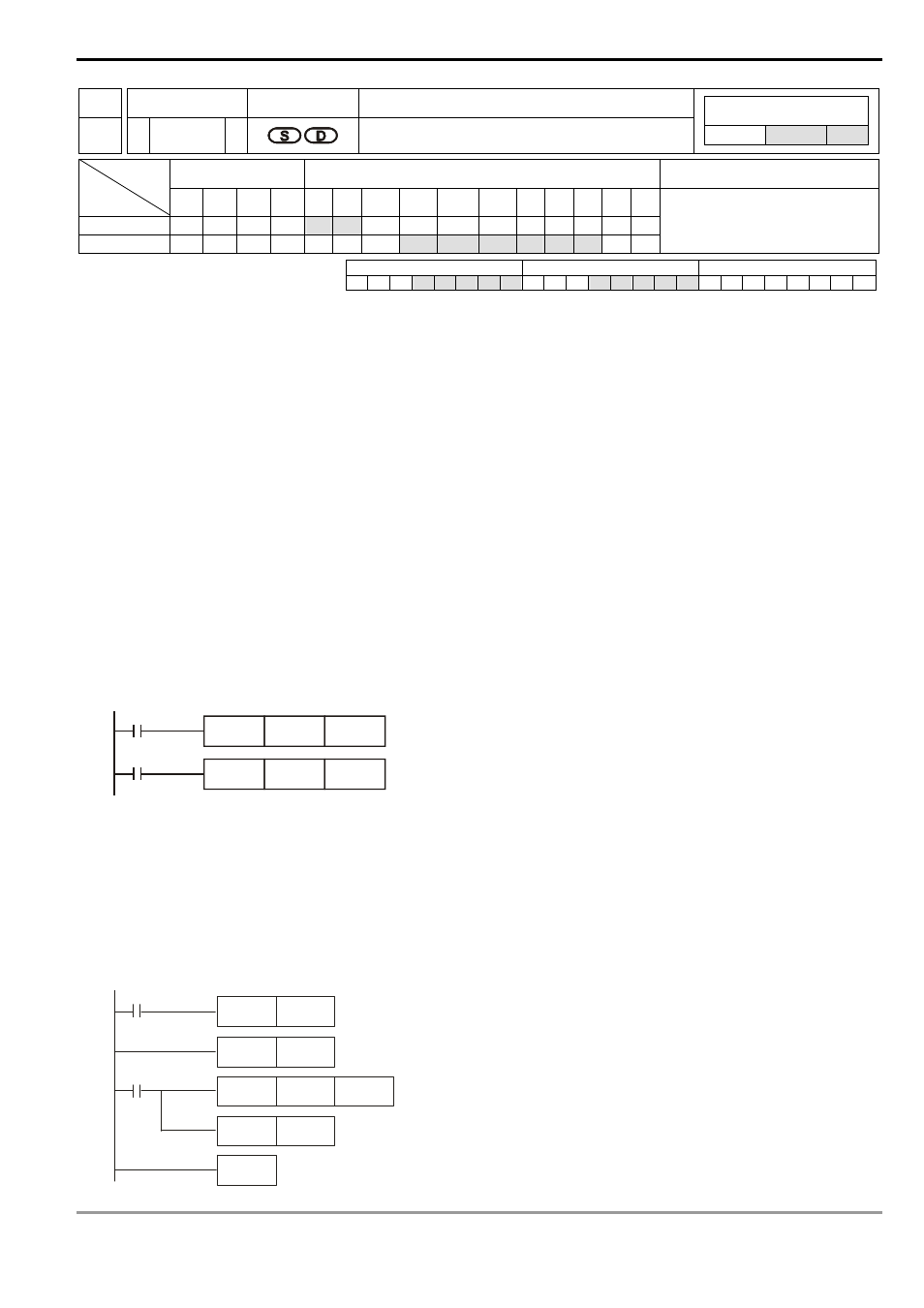
Program Example 1:
1. When X0 = On, VR0 volume changed will be converted into an 8-bit BIN value (0 ~ 255) and stored in D0.
2. When X1 = On, the imer T0 will start to time with the content in D0 as the set value in the timer.
X1
TMR
T0
D0
X0
VRRD
K0
D0
Program Example 2:
1. Read the VR volume in order: The VR0 ~ VR7 rotary switches on the PLC correspond to S = K0 ~ K7 of VRRD
instruction. E index register modification is used in the example below, K0E = K0 ~ K7.
2. The timer converts the scale 0 ~ 10 on the rotary switch into 0 ~ 255. The timing unit of T0 ~ T7 is 0.1 second;
therefore, the set time in the timer will be 0 ~ 25.5 seconds.
M1000
RST
E
F OR
K8
M1000
VRRD
INC
E
D100E
NEXT
K 0E