2 functions of devices in dvp-plc – Delta Electronics Programmable Logic Controller DVP-PLC User Manual
Page 112
2 Functions of Devices in DVP-PLC
DVP-PLC Application Manual
2-84
2.
See API 109 SWRD for more details.
3.
When PLC is in RUN status with 4DI card inserted into the input AX0 (photocoupler isolation), the status of AX0
~ AX3 correspond respectively to M1104 ~ M1107.
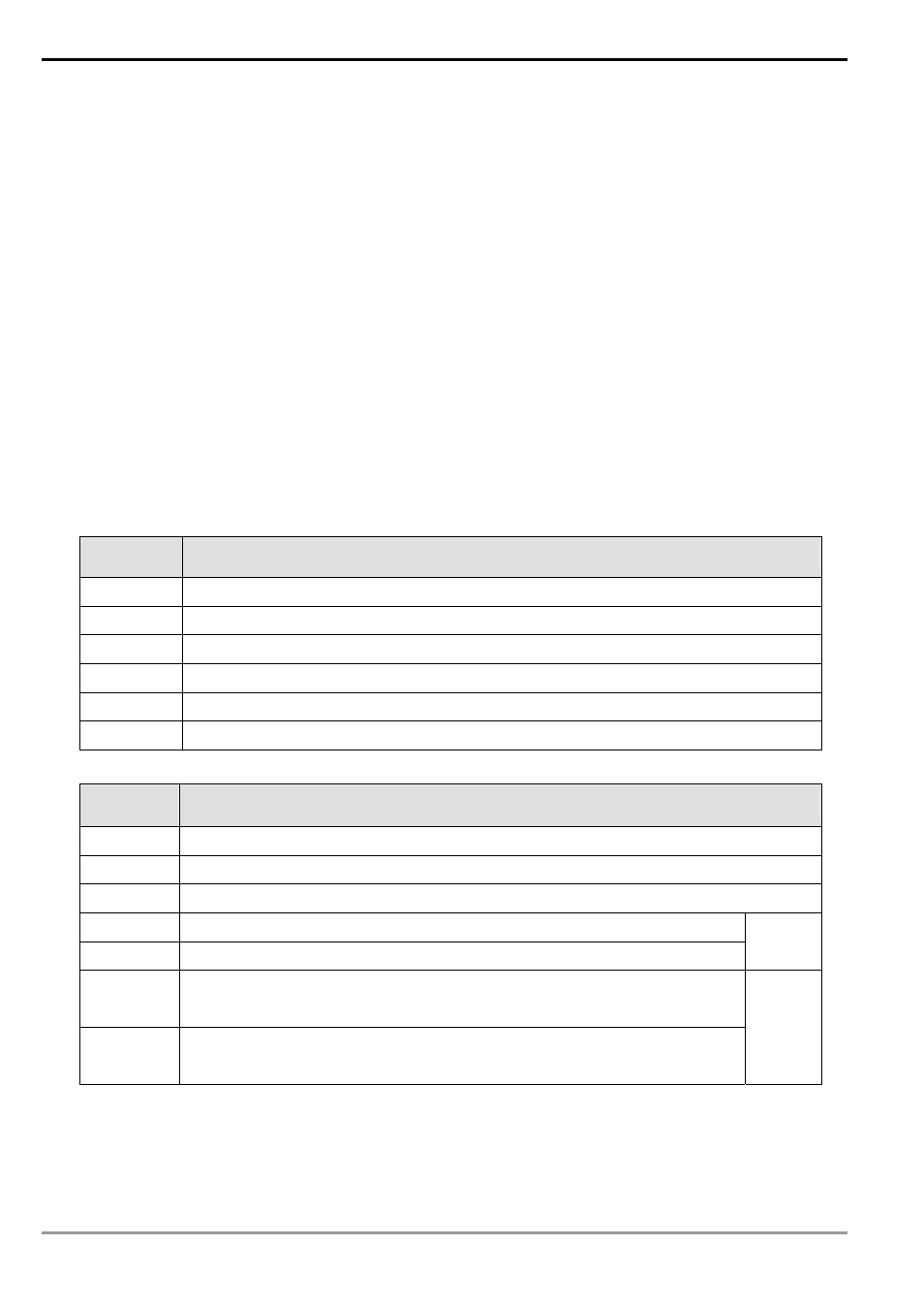
Function Group
Transistor Output Function Card
Number
M1112, M1113
Contents:
When PLC is in RUN status with 2DO function card inserted, M1112 and M1113 will correspond respectively to 2
transistors output points, AY0 and AY1.
Function Group
Pulse Output With Speed Acceleration/Deceleration
Number
M1115 ~ M1119, D1104
Contents:
1.
Special D and special M for acceleration/ deceleration of speed pulse output for SA/SX/SC (not applicable to
SC_V1.4 and versions above):
Device No.
Function
M1115 Activation
switch
M1116 “Accelerating”
flag
M1117
“Target frequency reached” flag
M1118 “Decelerating”
flag
M1119 “Function
completed”
flag
D1104
Start No. of control register (D)
2.
Parameters for D1104 (frequency range: 25Hz ~ 10KHz)
Index
Function
+ 0
Start frequency (SF)
+ 1
Gap frequency (GF)
+ 2
Target frequency (TF)
+ 3
The lower 16 bits of the 32 bits for the total number of output pulses
+ 4
The higher 16 bits of the 32 bits for the total number of output pulses
(TP)
+ 5
The lower 16 bits of the 32 bits for the total number of output pulses in
accelerating/decelerating section
+ 6
The higher 16 bits of the 32 bits for the total number of output pulses in
accelerating/decelerating section
(AP)
3.
No instruction is needed, users need only to fill out the parameter table and enable M1115 (in RUN mode). This
functio only supports Y0 output and the timing chart is as below.