Delta Electronics Programmable Logic Controller DVP-PLC User Manual
Page 266
6 Application Instructions API 00-49
DVP-PLC Application Manual
6-54
API Mnemonic
Operands
Function
37
WSFL P
Word Shift Left
Controllers
ES/EX/SS SA/SX/SC EH/SV
Bit Devices
Word Devices
Program Steps
Type
OP
X Y M S K H
KnX
KnY
KnM KnS T C D E F
S
*
*
*
*
*
*
*
D
*
*
*
*
*
*
n
1
* *
n
2
* *
WSFL, WSFLP: 9 steps
PULSE 16-bit 32-bit
ES EX SS SA SX SC EH SV ES EX SS SA SX SC EH SV ES EX SS SA SX SC EH SV
Operands:
S
: Start No. of the shifted device D: Start No. of the device to be shifted n
1
: Length of data to be shifted
n
2
: Number of words to be shifted in 1 shift
Explanations:
1.
The type of devices designated by S and D has to be the same, e.g. K
n
X, K
n
Y, K
n
M, and K
n
S as a category and
T, C, and D as another category.
2.
Provided the devices designated by S and D belong to K
n
type, the number of digits of K
n
has to be the same.
3. Range
of
n
1
: 1~ 512
4. Range
of
n
2
: 1 ~ n
1
5.
See the specifications of each model for their range of use.
6.
This instruction shifts the stack data of n
1
words starting from D to the left for n
2
words. S is shifted into D for n
2
words to supplement empty words.
7.
This instruction adopts pulse execution instructions (WSFLP)
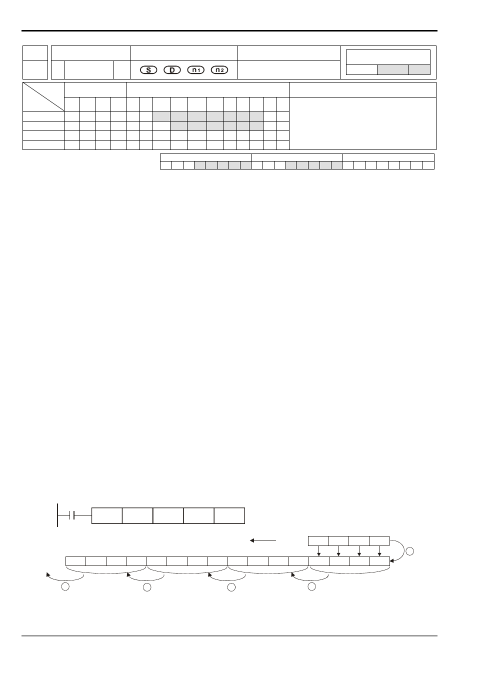
Program Example:
1.
When X0 = Off→On, the 16 register stack data composed of D20 ~ D35 will shift to the left for 4 registers.
2.
The figure below illustrates the left shift of the words in one scan.
n
D35 ~ D32 → carry
o
D31 ~ D28 → D35 ~ D32
p
D27 ~ D24 → D31 ~ D28
q
D23 ~ D20 → D27 ~ D24
r
D13 ~ D10 → D23 ~ D20 completed
1
3
4
5
2
Carry
X0
WSFLP
D10
K16
D20
K4
D13
D12 D11 D10
D35 D34 D33 D32 D31 D30 D29 D28 D27 D26
D25
D24 D23
D22
D21 D20
Left-shifiting for 4 registers