Delta Electronics Programmable Logic Controller DVP-PLC User Manual
Page 476
9 Application Instructions API 150-199
DVP-PLC Application Manual
9-4
10. RTU Mode: When PLC is connected to VFD-S AC motor drive
PLC
Ö VFD-S, PLC sends: “01 03 2100 0006 CF F4”
VFD-S
Ö PLC, PLC receives: “01 03 0C 0000 0503 0BB8 0BB8 0000 012D 8E C5”
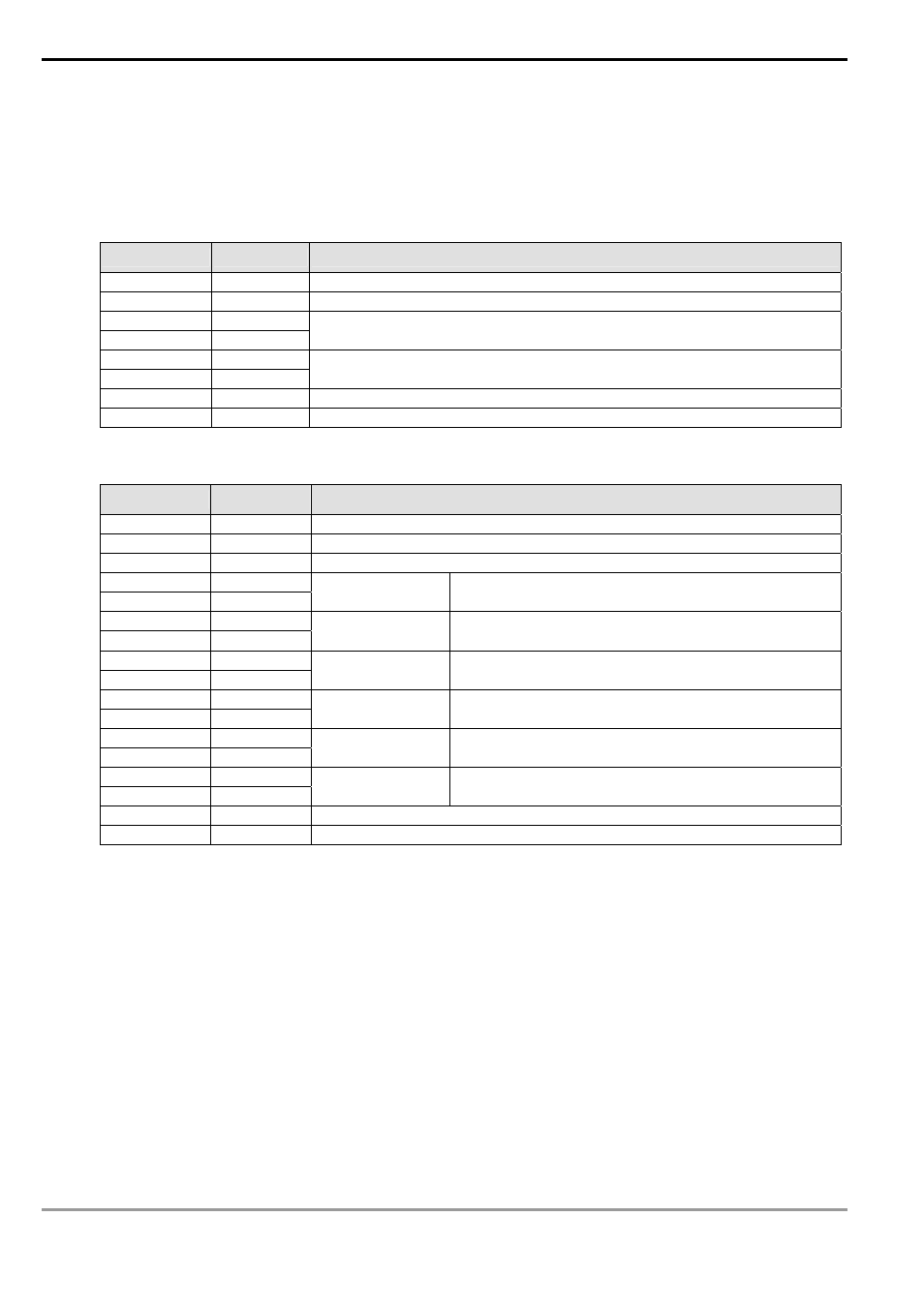
Registers for sent data (sending messages)
Register
DATA
Explanation
D1256 Low
01 H
Address
D1257 Low
03 H
Function
D1258 Low
21 H
D1259 Low
00 H
Starting Data Address
D1260 Low
00 H
D1261 Low
06 H
Number of Data (counted by words)
D1262 Low
CF H
CRC CHK Low
D1263 Low
F4 H
CRC CHK High
Registers for received data D0 (responding messages)
Register
DATA
Explanation
D0 Low
01 H
Address
D1 Low
03 H
Function
D2 Low
0C H
Number of Data (byte)
D3 Low
00 H
D4 Low
00 H
Content of
address 2100H
PLC automatically convert ASCII codes to numerals and
store the numeral in D1296 = H0000
D5 Low
05 H
D6 Low
03 H
Content of
address 2101H
PLC automatically convert ASCII codes to numerals
and store the numeral in D1297 = H0503
D7 Low
0B H
D8 Low
B8 H
Content of
address 2102H
PLC automatically convert ASCII codes to numerals
and store the numeral in D1298 = H0BB8
D9 Low
0B H
D10 Low
B8 H
Content of
address 2103H
PLC automatically convert ASCII codes to numerals
and store the numeral in D1299 = H0BB8
D11 Low
00 H
D12 Low
00 H
Content of
address 2104H
PLC automatically convert ASCII codes to numerals
and store the numeral in D1300 = H0000
D13 Low
01 H
D14 Low
2D H
Content of
address 2105H
PLC automatically convert ASCII codes to numerals
and store the numeral in D1301 = H012D
D15 Low
8E H
CRC CHK Low
D16 Low
C5 H
CRC CHK High
Program Example 2:
1.
Function code K6(H6): For writing a word data to register
When PLC is connected to VFD-S AC motor drive: M1143 = Off, in ASCII mode
When PLC is connected to VFD-S AC motor drive: M1143 = On, in RTU mode
2.
When in ASCII mode, the user stores the data to be written in the designated register D50 in hex format. The
data sent back from AC motor drive are stored in D1070 ~ D1076.
3.
When in RTU mode, the user stores the data to be written in the designated register D50 in hex format. The
data sent back from AC motor drive are stored in D1070 ~ D1077.
4.
When In ASCII mode or RTU mode, PLC will store the data to be sent in D1256 ~ D1295. If necessary, the
user can move the data to other general registers by using MOV, DMOV or BMOV instruction. Other
instructions of ES/EX/SS do not function on the data in D1256 ~ D1295.