Delta Electronics Programmable Logic Controller DVP-PLC User Manual
Page 433
8 Application Instructions API 100-149
DVP-PLC Application Manual
8-31
API Mnemonic
Operands
Function
120
D EADD P
Floating Point Addition
Controllers
ES/EX/SS SA/SX/SC EH/SV
Bit Devices
Word Devices
Program Steps
Type
OP
X Y M S K H
KnX KnY KnM KnS T
C
D
E
F
S
1
*
*
*
S
2
*
*
*
D
*
DEADD, DEADDP: 13 steps
PULSE 16-bit 32-bit
ES EX SS SA SX SC EH SV ES EX SS SA SX SC EH SV ES EX SS SA SX SC EH SV
Operands:
S
1
: Summand S
2
: Addend D: Sum
Explanations:
1. See the specifications of each model for their range of use.
2. Flags: M1020 (zero flag); M1021 (borrow flag); M1022 (carry flag)
3. S
1
+ S
2
= D. The floating point value in the register designated by S
1
and S
2
are added up and the result is
stored in the register designated by D. The addition is conducted in binary floating point system.
4. If
S
1
or S
2
is an designated constant K or H, the instruction will convert the constant into a binary floating point
value before the operation.
5. S
1
and S
2
can designate the same register. In this case, if the “continuous execution” instruction is in use,
during the period when the criteria contact in On, the register will be added once in every scan by pulse
execution instruction DEADDP.
6. If the absolute value of the result > maximum floating point available, the carry flag M1022 = On.
7. If the absolute value of the result < minimum floating point available, the borrow flag M1021 = On.
8. If the result = 0, the zero flag M1020 = On.
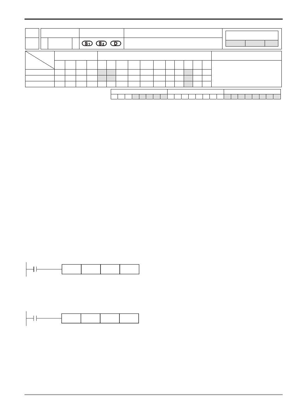
Program Example 1:
When X0 = On, binary floating point (D1, D0) + binary floating point (D3, D2) and the result is stored in (D11, D10).
D0
DEADD
X0
D2
D10
Program Example 2:
When X2 = On, binary floating point (D11, D10) + K1234 (automatically converted into binary floating point) and the
result is stored in (D21, D20).
D10
DEADD
X2
K1234
D20
Remarks:
For floating point operations, see “5.3 Handling of Numeric Values”.