Delta Electronics Programmable Logic Controller DVP-PLC User Manual
Page 442
8 Application Instructions API 100-149
DVP-PLC Application Manual
8-40
API
Mnemonic Operands
Function
128
D POW P
Floating Point Power Operation
Controllers
ES/EX/SS SA/SX/SC EH/SV
Bit Devices
Word Devices
Program Steps
Type
OP
X Y M S K H
KnX
KnY KnM KnS T
C
D
E
F
S
1
*
*
*
S
2
*
*
*
D
*
DPOW, DPOWP: 13 steps
PULSE 16-bit 32-bit
ES EX SS SA SX SC EH SV ES EX SS SA SX SC EH SV ES EX SS SA SX SC EH SV
Operands:
S
1
: Device for base. S
2
: Device for exponent. D: Device for operation result
Explanations:
1. See the specifications of each model for their range of use.
2. This instruction performs power multiplication of binary floating point S
1
and S
2
and stores the result in D.
D
= POW[S
1
+ 1, S
1
]
^[S
2
+ 1, S
2
]
3. Only positives are valid for the content in S
1
. Both positives and negatives are valid for the content in S
2
. When
designating D registers, the data should be 32-bit and the operation should be performed in floating point
system. Therefore, S
1
and S
2
should be converted into floating point values.
Example: When S
1
S2
= D, D = ?
Assume S
1
= 5, S
2
= 3, D = 5
3
=125
4. If the absolute value of the result > maximum floating point available, the carry flag M1022 = On.
5. If the absolute value of the result < minimum floating point available, the borrow flag M1021 = On.
6. If the result = 0, the zero flag M1020 = On.
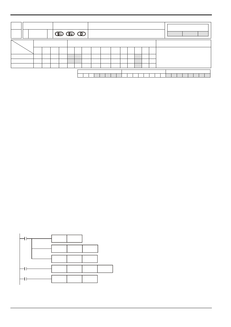
Program Example:
1. When M0 = On, convert (D1, D0) and (D3, D2) into binary floating points and store them in the 32-bit registers
(D11, D10) and (D13, D12).
2. When M1= On, perform POW operation on the binary floting points in 32-bit registers (D11, D10) and (D13,
D12) and store the result in the 32-bit register (D21, D20).
3. When M2 = On, convert the binary floating point (D21, D20) into decimal floating point (D30 × 10
[D31]
) and store
it in register (D31, D30).
M0
RST
M1081
M1
D10
D12
M2
DEBCD
D20
D30
D2
D12
D20
DFLT
DFLT
DPOW
D0
D10
Remarks: