Delta Electronics Programmable Logic Controller DVP-PLC User Manual
Page 358
7 Application Instructions API 50-99
D V P - P L C A P P L I C AT I O N M A N U A L
7-74
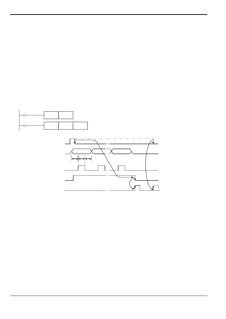
Program Example 2:
1. PR instruction is for outputing a string of 8 bits. When the special auxiliary relay M1027 = Off, PR is able to
execute an output of maximum 8 letters in string. When M1027 = On, PR is able to execute an output of 1 ~ 16
letters in string.
2. When M1027 = On and X10 goes from Off to On, the instruction will be executed. Designate Y10 (low bits) ~ Y17
(high bits) as the data output points and Y20 for scan signals. Designate Y21 for the monitor signals during the
execution. In this mode, you can execute an output for 16 letters in sequence. During the output, if the drive
contact goes Off, the data output will stop after it is completed.
3. When the string encounters 00H (NUL), the string output will finish. The letters coming after it will not be
processed.
4. When X10 goes from On to Off, the data output will automatically stop after one cycle. If X10 keeps being On,
M1029 will not be enabled.
X10
PR
D0
Y10
M1002
SET
M1027
T
T
T
X10 start signal
Y10 ~ Y17 data
Y20 scan signal
Y21 being executed
M1029 (execution completed)
First letter
Last letter
T: scan time or the time of
the inserted interruption
Remarks:
1. Please use transistor output for the output designated by this instruction.
2. When using this instruction, please fix the scan time or place this instruction in a timed interruption subroutine.