Delta Electronics Programmable Logic Controller DVP-PLC User Manual
Page 430
8 Application Instructions API 100-149
DVP-PLC Application Manual
8-28
API Mnemonic Operands
Function
118
D EBCD P
Float to Scientific Conversion
Controllers
ES/EX/SS SA/SX/SC EH/SV
Bit Devices
Word Devices
Program Steps
Type
OP
X Y M S K H
KnX
KnY KnM KnS T
C
D
E
F
S
*
D
*
DEBCD, DEBCDP: 9 steps
PULSE 16-bit 32-bit
ES EX SS SA SX SC EH SV ES EX SS SA SX SC EH SV ES EX SS SA SX SC EH SV
Operands:
S
: Source D: Result
Explanations:
1. See the specifications of each model for their range of use.
2. Flags: M1020 (zero flag); M1021 (borrow flag); M1022 (carry flag)
3. This instruction converts binary floating point value in the register designated by S into decimal floating point
value and stores it in the register designated by D.
4. PLC conducts floating point operation in binary format. DEBCD instruction is exclusively for converting floating
points from binary to decimal.
5. If the absolute value of the result > maximum floating point available, the carry flag M1022 = On.
6. If the absolute value of the result < minimum floating point available, the borrow flag M1021 = On.
7. If the result = 0, the zero flag M1020 = On.
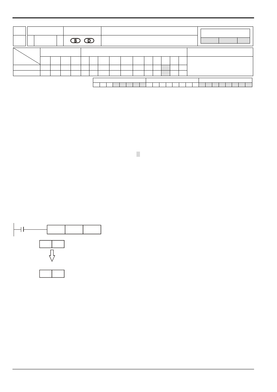
Program Example:
When X0 = On, the binary floating points in D1 and D0 will be converted into decimal floating points and stored in D3
and D2.
D0
DEBCD
X0
D2
D0
D1
D2
D3
Binary
Floating Point
32 bits for real number, 8 bits for exponent
1 bit for symbol bit
[D2] * 10
[D3]
Decimal
Floating Point
32 bits for real number, 8 bits for exponent
1 bit for symbol bit
Exponent Real number
Exponent
Real number
Remarks:
For floating point operations, see “5.3 Handling of Numeric Values”.