Delta Electronics Programmable Logic Controller DVP-PLC User Manual
Page 486
9 Application Instructions API 150-199
DVP-PLC Application Manual
9-14
API Mnemonic
Operands
Function
155
D ABSR
Read the Absolute Position from a Servo
Motor
Controllers
ES/EX/SS SA/SX/SC EH/SV
Bit Devices
Word Devices
Program Steps
Type
OP
X Y M S K H
KnX
KnY KnM KnS T
C
D
E
F
S
*
*
*
*
D
1
*
*
*
D
2
*
*
*
*
*
*
*
DABSR: 13 steps
PULSE 16-bit 32-bit
ES EX SS SA SX SC EH SV ES EX SS SA SX SC EH SV ES EX SS SA SX SC EH SV
Operands:
S: Input signal from Servo (occupies 3 consecutive devices) D
1
: Control signal for controlling Servo (occupies 3
consecutive devices) D
2
: Absolute position data (32-bit) read from Servo
Explanations:
1.
Operand S and D
1
of SA series MPU do not support E, F index register modification.
2.
See the specifications of each model for their range of use.
3.
This instruction can only be used once in the program.
4.
Flag: see remarks for more details.
5.
This instruction reads the absolute position (ABS) of MITSUBISHI MR-J2 servo drive (with absolute position
check function).
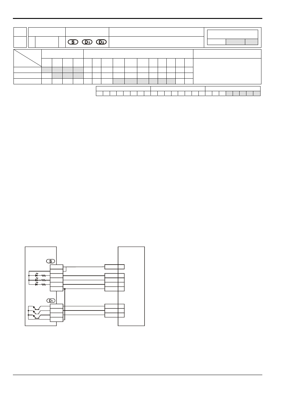
6.
S will occupy 3 consecutive devices, S, S +1, and S +2. S and S +1 are connected to the absolute position (bit
0, bit 1) on the servo for data transmitting. S +2 is connected to Servo for transmitting data ready flag. See the
wiring example below for more details.
7.
D
1
will occupy 3 consecutive devices, D
1
, D
1
+ 1, D
1
+ 2. D
1
is connected to SERVO On (SON) of Servo. D
1
+1 is
connected to ABS transmisstion mode of Servo and D
1
+2 is connected to ABS request signal. See the wiring
example below for more details.
PLC
DVP32EH00T
ABS(bit 0)
ABS(bit 1)
SERVO ON
SERVO AMP
MR-J2-A
CN1B
D01
4
19
10
6
ZSP
TLC
SG
5
8
9
SON
ABSM
ABSR
X0
X1
X2
24G
S/S
+24V
Y4
Y5
Y6
C4
VDD
3
transmission data is ready
ABS request
ABS transmission mode
8.
D
2
will occupy 2 consecutive devices D
2
and D
2
+ 1. D
2
is the lower 16 bits and D
2
+ 1 is the higher 16 bits. The
absolute position data should be written into the present value registers (D1337, D1336) of CH0 pulse (Y0, Y1)
or the present value registers (D1339, D1338) of CH1 pulse (Y2, Y3) in EH series MPU; therefore, we suggest
you designate the two corresponding registers. If you designate other devices as the registers, you still have to