Delta Electronics Programmable Logic Controller DVP-PLC User Manual
Page 466
8 Application Instructions API 100-149
DVP-PLC Application Manual
8-64
b) When Y0 = On and Y1 = Off: Valve “open”
c) When Y0 = Off and Y1 = On: Valve “closed”
d) When Y0 and Y1 = On: The action is prohibited.
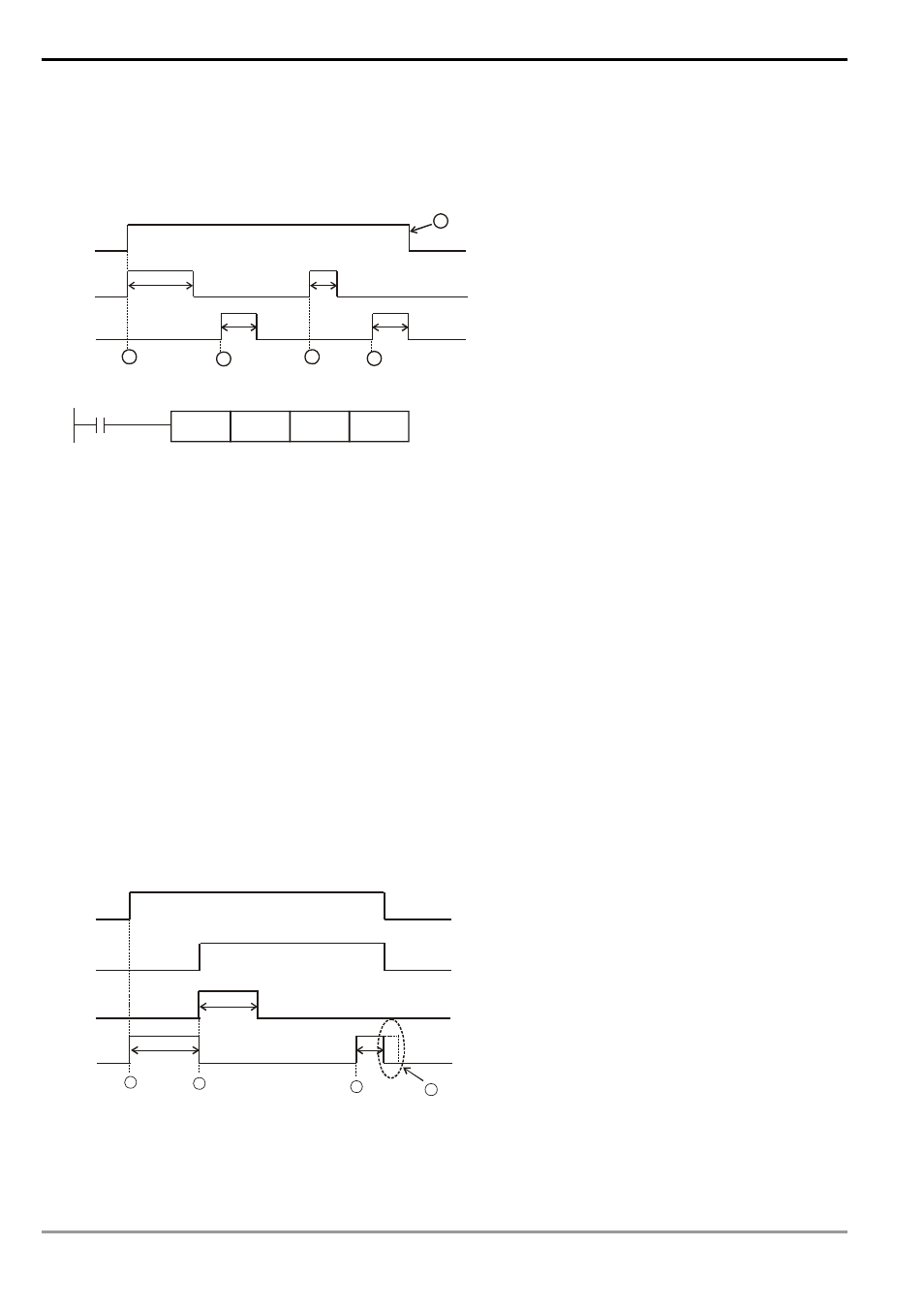
3. Timing diagram and program of the control:
M0
Y0
Y1
D0=k40
D0=k20
D0=k30 D0=k10
4sec
2sec
1sec
2sec
1
2
3
4
5
M0
CVM
D0
K50
Y0
4. Control
phases:
1) Phase
1
: When M0 = On, D0 = K40 refers to the valve shall be open (Y0 = On, Y1 = Off) till the position of
4 seconds.
2) Phase
2
: Change the position of the valve and D0 = K20. Due to that the previous position was at 4
seconds, the valve shall be closed (Y0 = Off, Y1 = On) for 2 seconds, moving the valve to the position of 2
seconds.
3) Phase
3
: Change the position of the valve and D0 = K30. Due to that the previous position was at 2
seconds, the valve shall be open (Y0 = On, Y1 = Off) for 1 second, moving the valve to the position of 3
seconds.
4) Phase
4
: Change the position of the valve and D0 = K10. Due to that the previous position was at 2
seconds, the valve shall be closed (Y0 = Off, Y1 = On) for 2 seconds, moving the valve to the position of 1
second.
5) Phase
5
: Switch off X0 and no actions at the valve (Y0 = Off, Y1 = Off).
Program Example 2:
1. Timing diagram and program of the control:
Y0
Y1
D0=k40
D0=k10
4sec
2sec
1
2
3
4
M0
T0
5sec
D0=1