1 basic principles of plc ladder diagram, 1 the working principles of ladder diagram, Foreword: background and functions of plc – Delta Electronics Programmable Logic Controller DVP-PLC User Manual
Page 5
1 Basic Principles of PLC Ladder Diagram
DVP-PLC Application Manual
1-1
Foreword: Background and Functions of PLC
PLC (Programmable Logic Controller) is an electronic device, previously called “sequence controller”. In 1978,
NEMA (National Electrical Manufacture Association) in the United States officially named it as “programmable logic
controller”. PLC reads the status of the external input devices, e.g. keypad, sensor, switch and pulses, and execute by
the microprocessor logic, sequential, timing, counting and arithmetic operations according the status of the input
signals as well as the pre-written program stored in the PLC. The generated output signals are sent to output devices
as the switch of a relay, electromagnetic valve, motor drive, control of a machine or operation of a procedure for the
purpose of machine automation or processing procedure. The peripheral devices (e.g. personal computer/handheld
programming panel) can easily edit or modify the program and monitor the device and conduct on-site program
maintenance and adjustment. The widely used language in designing a PLC program is the ladder diagram.
With the development of the electronic technology and wider applications of PLC in the industry, for example in
position control and the network function of PLC, the input/output signals of PLC include DI (digital input), AI (analog
input), PI (pulse input), NI (numeric input), DO (digital output), AO (analog output), and PO (pulse output). Therefore,
PLC will still stand important in the industrial automation field in the future.
1.1 The Working Principles of Ladder Diagram
The ladder diagram was a diagram language for automation developed in the WWII period, which is the oldest
and most widely adopted language in automation. In the initial stage, there were only A (normally open) contact, B
(normally closed) contact, output coil, timer and counter…the sort of basic devices on the ladder diagram (see the
power panel that is still used today). After the invention of PLC, the devices displayable on the ladder diagram are
added with differential contact, latched coil and the application commands which were not in a traditional power panel,
for example the addition, subtraction, multiplication and division operations.
The working principles of the traditional ladder diagram and PLC ladder diagram are basically the same. The
only difference is that the symbols on the traditional ladder diagram are more similar to its original form, and PLC
ladder diagram adopts the symbols that are easy to recognize and shown on computer or data sheets. In terms of the
logic of the ladder diagram, there are combination logic and sequential logic.
1. Combination
Logic
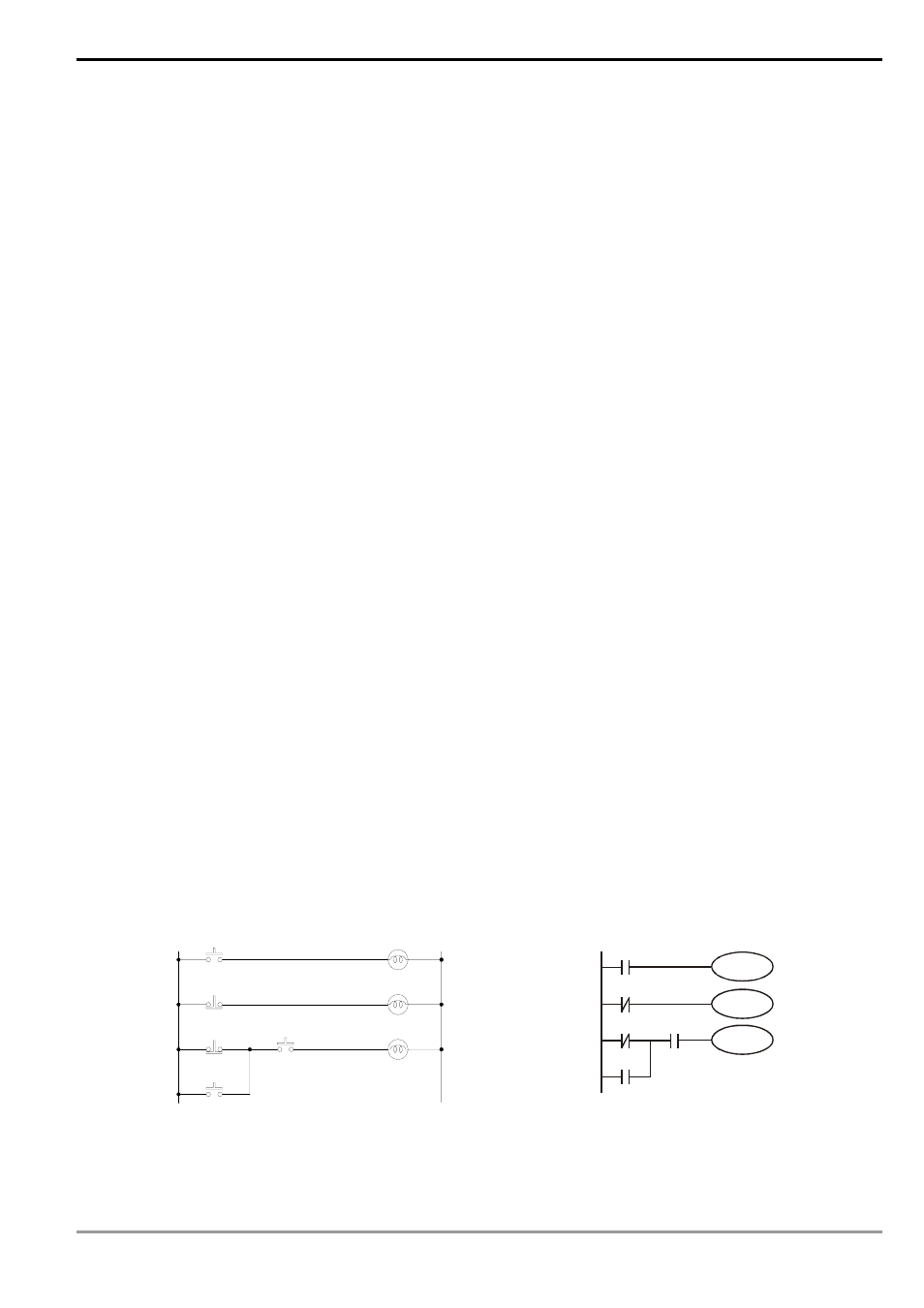
Examples of traditional ladder diagram and PLC ladder diagram for combination logic:
Traditional Ladder Diagram
PLC Ladder Diagram
X4
X0
X2
X3
X1
Y0
Y2
Y1
X0
Y0
X1
Y1
Y2
X2
X3
X4
Row 1: Using a normally open (NO) switch X0 (“A” switch or “A" contact). When X0 is not pressed, the contact
will be open loop (Off), so Y0 will be Off. When X0 is pressed, the contact will be On, so Y0 will be On.