Delta Electronics Programmable Logic Controller DVP-PLC User Manual
Page 363
7 Application Instructions API 50-99
D V P - P L C A P P L I C AT I O N M A N U A L
7-79
M1002
TO
K1
K1
H10
K1
TO
K1
K33
H0
K1
X0
TO
K1
K23
K400
K1
TO
K1
K29
K3600
K1
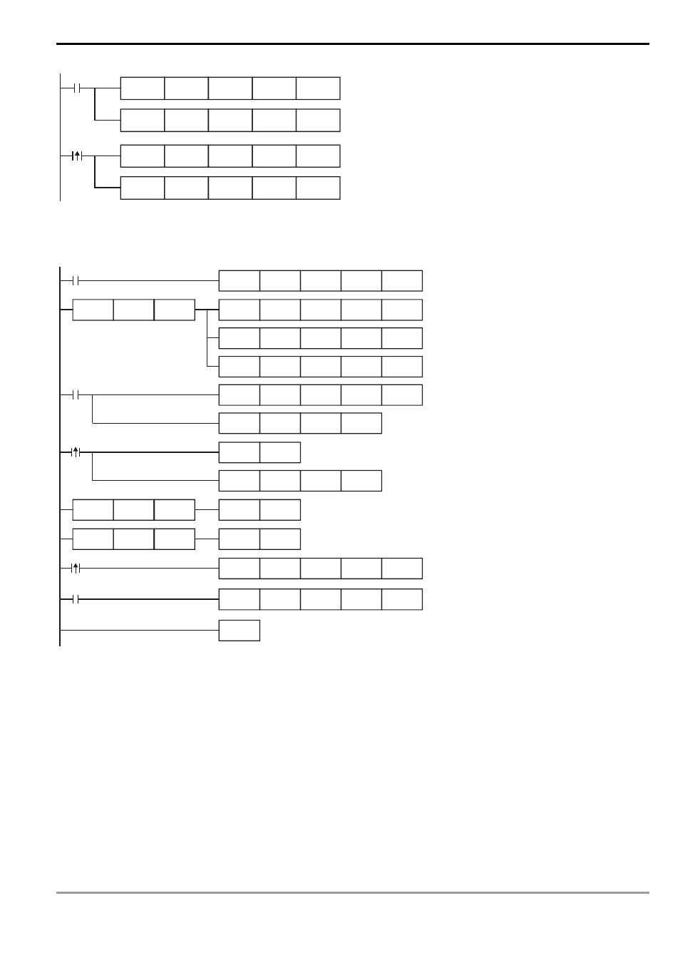
FROM/TO Application Example 5:
When DVP-04AD-S is used with DVP-02DA-S
M1000
FROM
K0
K0
D0
K1
TO
K0
K1
H3030
K1
LD=
H88
D0
TO
K0
K2
K32
K2
FROM
K0
K6
D20
K4
M1000
FROM
K1
K0
D0
K1
CMP
H49
D0
M0
M1013
INC
D100
ADD
D101
K5
D101
RST
D100
LD=
K4000
D100
RST
D101
LD=
K4000
D101
M1
TO
K1
K1
H10
K1
M1
TO
K1
K10
D100
K2
END
1. Read CR#0 of the extension module No. 0 and see if it is DVP-04AD-S: H88.
2. If D0 = H88, set the input modes: (CH1, CH3) mode 0, (CH2, CH4) mode 3.
3. Set the average times in CH1 and CH2 from CR#2 and CR#3 as K32.
4. Read the average of input signals at CH1 ~ CH4 from CR#6 ~ CR#9 and store the 4 data in D20 ~ D23.
5. Read CR#0 of the extension module No. 1 and see if it is DVP-02DA-S: H49.
6. D100 increases K1 and D101 increases K5 every second.
7. When D100 and D101 reach K4,000, they will be cleared as 0.
8. See if the model is DVP-02DA-S when M1 = On. If so, set up output mode: CH1 in mode 0 and CH2 is mode 2.
9. Write the output settings of D100 and D101 into CR#10 and CR#11. The analog output will change by the
changes in D100 and D101.