Delta Electronics Programmable Logic Controller DVP-PLC User Manual
Page 411
8 Application Instructions API 100-149
DVP-PLC Application Manual
8-9
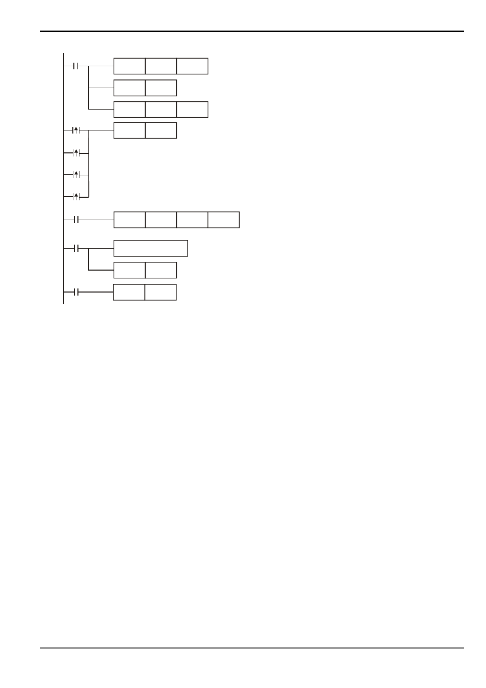
M1002
MOV
H87
D1120
SET
M1120
SET
M1122
MOV
K100
D1129
RST
M1127
M1127
X0
MODWR
K1
H0100
H1770
X0
M1129
M1140
M1141
RST
M1129
Set up communication protocol to 9600, 8, E, 1
Retain communication protocol
Set up communication time-out: 100ms
Set up communication instruction:
device address 01, data address H0100 data H1770
Communication time-out Retry
Data receiving error Retry
Sending address error Retry
receiving completed
handle received data
The received data are stored in D1070 ~ D1085 in ASCII format.
Sending/receiving of data is completed. The flag is reset.
Communication time-out. The flag is reset.
M1127
M1129
Set up transmission request
Program Example 4:
1. In the communication between PLC and VFD-S series AC motor drive (ASCII Mode, M1143 = Off), retry when
communication time-out, data receiving error and sending address error occur. Times of retry = D0 (default = 3).
When communication Retry is successful, the user can return to controlling by triggering criteria.
2. When X0 = On, PLC will write H1770(K6000) into VFD-S data adress H0100 of device 01.
3. M1129 will be On when communication time-out occurs. The program will trigger M1129 and send request to
M1122 for writing the data again. Times of Retry = D0 (default = 3)
4. M1140 will be On when data receiving error occurs. The program will trigger M1140 and send request to M1122
for writing the data again. Times of Retry = D0 (default = 3)
5. M1141 will be On when sending address error occurs. The program will trigger M1141 and send request to
M1122 for writing the data again. Times of Retry = D0 (default = 3)