Delta Electronics Programmable Logic Controller DVP-PLC User Manual
Page 534
9 Application Instructions API 150-199
DVP-PLC Application Manual
9-62
API Mnemonic
Operands
Function
182
MXOR P
Matrix ‘XOR’ Operation
Controllers
ES/EX/SS SA/SX/SC EH/SV
Bit Devices
Word Devices
Program Steps
Type
OP
X Y M S K H
KnX
KnY KnM KnS T
C
D
E
F
S
1
*
*
*
*
*
*
*
S
2
*
*
*
*
*
*
*
D
*
*
*
*
*
*
n
*
*
*
MXOR, MXORP: 9 steps
PULSE 16-bit 32-bit
ES EX SS SA SX SC EH SV ES EX SS SA SX SC EH SV ES EX SS SA SX SC EH SV
Operands:
S
1
: Matrix source device 1 S
2
: Matrix source device 2 D: Operation result n: Array length
Explanations:
1. Range
of
n: K1 ~ K256
2.
S
1
, and S
2
designate KnX, KnY, KnM and KnS; D designates KnYm KnM and KnS
3.
SA/SX/SC can designate n = 4. EH/EH2/SV can designate n
4
≦ .
4.
See the specifications of each model for their range of use.
5.
The two matrix sources S
1
and S
2
perform matrix ‘XOR’ operation according to the array length n. The result is
stored in D.
6.
Operation rule of matrix ‘XOR’: The result will be 1 if the two bits are different. The result will be 0 if the two bits
are the same.
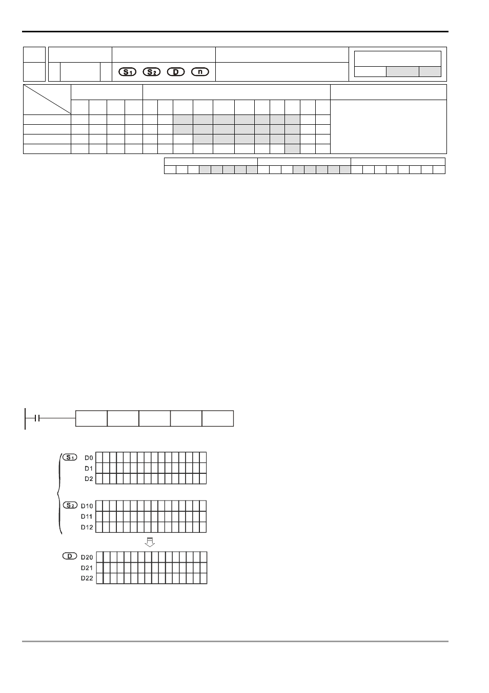
Program Example:
When X0 = On, the 3 arrays of 16-bit registers D0 ~ D2 and the 3 arrays of 16-bit registers D10 ~ D12 will perform a
matrix ‘XOR’ operation. The result will be stored in the 3 arrays of 16-bit registers D20 ~ D22.
X0
MXOR
D0
D10
D20
K3
1
1
1
0
0
0
1
1
0
0 0
0
1
1
0
0
0
1
1
0
0 0
0
1
1
0
0
0
1
1
0
0 0
0
0
1
0
1
0
1
0
1
0
1
0
1
0
1
0
1
0
1
0
1
0
1
0
1
0
1
0
1
0
1
0
1
0
1
0
1
0
1
0
1
0
1
0
1
0
1
0
1
1
1
1
1
1
0
0
0
1
1
1
1
1
1
1
1
0
0
1
1
0
0
1
1
0
0
1
1
0
0
1
1
0
0
1
1
0
0
1
1
1
1
1
1
1
1
1
1
1
1
1
1
1
1
1
1
1
1
1
1
1
1
b15
b0
MOR
Before
Execution
After
Execution
MXOR