Making switcher processor gpi output settings – Sony Multi Interface Shoe Adapter User Manual
Page 990
Chapt
990
Interfacing With External Devices (Device Interface Menu)
Notes
• When the action is “Format,” these settings conflict with the current
settings, but after making the settings, agreement is restored after a pulse
change or power off/on.
• When the Action is “Bkgd A Side Flags” or “Bkgd B Side Flags,” the
levels are fixed, as follows.
High level: Off
Low level: On
Making Switcher Processor GPI Output Settings
1
In the Switcher >Device Interface menu, press [GPI Output].
The GPI Output menu appears.
2
Using any of the following methods, select the settings.
• Press directly on the list in the status area.
• Press the arrow keys to scroll the reverse video cursor.
• Turn the knob.
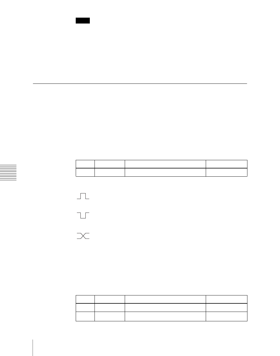
3
In the
(Rising Edge):
The trigger causes the relay contacts to be open-
circuit or drives the output high, and holds this state for the
specified pulse width.
(Falling Edge):
The trigger causes the relay contacts to be shorted
or drives the output low, and holds this state for the specified
pulse width.
(Any Edge):
Each time the trigger occurs, the relay contacts are
alternately closed or opened, or the output is switched between
high and low.
Status:
Depending on the status, the relay contacts are closed or opened,
or the output is switched between high and low.
No Operation:
The trigger has no effect on the output.
4
Turn the knobs to select the pulse width and timing to be set.
Knob
Parameter
Adjustment
Setting values
1
Port
Port selection
1 to 8
Knob
Parameter
Adjustment
Setting values
3
Pulse Width
Pulse width
1 to 60 (fields)
4
Timing
Output timing
1 to 3
a)