Making an external box setting, Making an external box setting 1 – Sony Multi Interface Shoe Adapter User Manual
Page 1031
1031
Router Interface Settings (Router Menu)
Chap
Compact (128
×
128):
Assign the switcher S-Bus space at compact size.
It is not possible to assign all switcher inputs and outputs to the S-Bus
space, but the S-Bus space can be used efficiently.
3
Turn the knobs to set the parameters for the following items.
Source:
Specify the start address of the matrix source.
Destination:
Specify the start address of the matrix destination.
Level:
Specify the level in the S-Bus space.
a) When the matrix size is Standard, the maximum value is 889. For the Compact size, the
maximum value is 897.
b) When the matrix size is Standard, the maximum value is 887. For the Compact size, the
maximum value is 897.
Making an External Box Setting
1
In the Router/Tally >Router menu, press [External Box Assign].
The External Box Assign menu appears.
The status area shows the external box size, address, and other settings.
2
In the
to 4).
3
In the
No Assign:
Do not use.
8×1:
Select an external box with 8 inputs and 1 output.
16×1:
Select an external box with 16 inputs and 1 output.
32×1:
Select an external box with 32 inputs and 1 output.
4
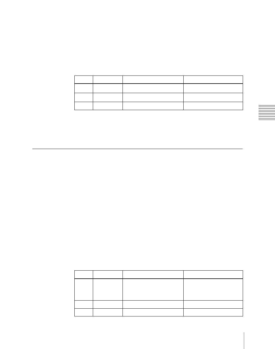
Turn the knobs to make adjustments.
Knob
Parameter
Adjustment
Setting values
1
Source
Source start address
1 and upwards
a)
2
Destination
Destination start address
1 and upwards
b)
3
Level
Level
1 to 8
Knob
Parameter
Adjustment
Setting values
1
Source
Source start address
1 to 1017
a)
1 to 1009
b)
1 to 993
c)
2
Destination
Destination start address
1 to 1024
3
Level
Level
1 to 8